Centralized substation protection and control
Centralized substation protection and control has been attempted in the past based on the available technology. This evolution is now at the intersection of sensing, protection and communication technologies, providing the unique opportunity to develop a more reliable and maintainable CPC system.
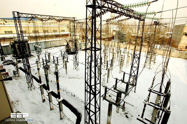 A case study of 110/10 kV substation with centralized protection and control (on photo: Altai closed electrical substation 110/10/6 kV; credit: inform.kz)
This article discusses a software based substation protection, automation, and control system (PACS), iSAS, developed by LYSIS LLC, Russia which is was at that time under trial operation at the 110/10 kV “Olympic” substation in the town of Surgut in northwest Siberia.
The philosophy of iSAS is based on PAC function element implementation as per IEC 61850 logical nodes (LN).
The software modules were developed independently of particular hardware and could be placed in dedicated IEDs as well as in one powerful computer. When the software modules are located in the same device they interact with each other through the iSAS software core over its internal mechanisms.
However, when they are distributed among various devices then they use Process and/or Station Bus communication services.
The decision about the allocation of functions depends on particular project requirements and performance of available hardware and resource consumption by software modules. Conformity to the IEC 61850 information model and configuration language (SCL) was one of the main priorities of the project.
Overview of iSAS project
iSAS is implemented in a PAC system for a 110/10 kV substation pilot project for one Russian Distribution System Operator (DSO) – Tumenenergo. The project is completely managed and implemented by iSAS’ software developer – LYSIS LLC.
The project has the following goals:
- Search for an optimal system architecture, methods and approaches for iSAS lifecycle management,
- Research and analyze system characteristics and behavior under real-life conditions,
- Provide technical and economic analysis at all stages of the system lifecycle, as well as comparison with conventional systems with similar functionality,
- Conduct a reliability analysis and comparison with a system with conventional architecture,
- Quantify the advantages and disadvantages of the PACS system, along with the suitability for the DSO to spread out such experience widely.
The selected 110/10 kV Olympic substation, for the pilot implementation of a centralized digital PAC system, contains two power transformers, two incoming 110 kV overhead power lines and 40 feeders connected to four 10 kV busbars.
According to the contract, the project had 5 phases:
- Design,
- Procurement, installation and testing,
- Trial operation of the system for one year,
- Analysis of regulators requirements, rules, and standards, and proposing amendments in these documents for homologation of software-based PAC systems in the Russian market, and
- Certification of measuring method for process bus-based systems with separate measuring (process interfacing devices, PID) and calculation (IEDs) parts.
At that time, LYSYS LLC has completed the design, procurement, installation and testing phases and the system has been put in trial operation. Phases 4 and 5 were completed by the end of 2015.
1. Protection subsystem
The single line diagram of the substation is shown in Figure 1.
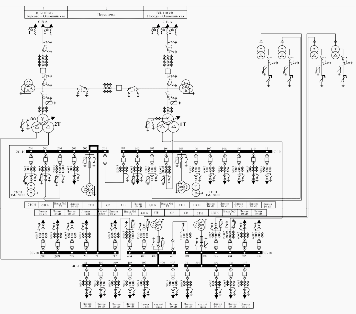
Protection and related automatics of the two 110 kV power lines include the following functions:
- Line Differential Protection(87L) include an equipment at the remote terminal,
- Three stages of Distance Protection (21P),
- Four stages of Ground (Earth) Overcurrent Protection (51N),
- Instantaneous Phase-to-phase Overcurrent Protection (50P),
- Automatic Reclosing (79), and
- Breaker Failure Protection (50BF).
110 kV busbars are protected by Busbar Differential Protection (87B) function.
110/10 kV Transformer protection and automatics contains following functions:
- Transformer Differential Protection (87T),
- Transformer Overload Protection (51),
- HV-side Time Overcurrent Protection (51P),
- LV-side Time Overcurrent Protection (51P), and
- Automated Voltage Regulator.
10 kV side of transformers connected bus-bars and Feeders are equipped with:
- Two stages Phase-to-phase Time Overcurrent Protection (51P),
- Breaker Failure Protection (50BF),
- Interlocking Overcurrent Busbar Protection,
- Automatic Closing of Bus-tie Breaker,
- Under Frequency Load Shedding, and
- Under Frequency Load Restoration.
2. Control subsystem
The control subsystem is associated with operator activity. It is aimed at primary equipment and process monitoring and control. The system includes following functions and possibilities:
- Control and state monitoring of all motorized switching apparatus, such as disconnectors, earth switches and circuit breakers,
- Providing one and two-step (select before operate) control models,
- Automatically performing predefined sequences of operational actions,
- Gathering of analog and discrete data of primary equipment and process parameters and their visual representation at HMIs,
- Access, retrieval and visual representation of archived data including alarm and event lists,
- Bay level and substation level interlocking,
- Transformer tap changer manual control, and
- Remote control of system parameters like settings of protection and control algorithms.
All the above control functions are accessible to operator via local HMIs as well through local and remote SCADA using the virtual telecontrol gateway provided by iSAS software.
3. Revenue Metering System
The revenue metering system was implemented in compliance with energy market rules and contains following functionalities:
- Active Energy and Power metering,
- Reactive Energy and Power metering,
- Energy and power are measured in both forward and reverse directions,
- Storing energy and power in 30 minute profiles for up to 150 days, and
- Integration of the system into existing DSO-scale metering and billing system.
4. Monitoring and Recording Subsystem
The monitoring and recording subsystem is comprised of two components – alarm and event management (AEM) and transient recording. AEM allows detection of the alarming state of monitored parameters and forms a record in alarm and event lists and archives.
Alarming state detection is based on a predefined configuration that includes logical scheme and activation conditions.
Some custom LNs were developed to model AEM functions as per IEC 61850. The alarm and event messages are logged and accessed by standard IEC 61850 Log service.
Fault recorder function is able to register currents, voltages, protection start and trip signals, primary equipment states and operational parameters etc. It is possible to register as raw instantaneous values as well as derived calculated parameters like RMS values. Performance and resolution of recording function is enough for recording transient processes like short circuits at monitored equipment.
Also, IEC 61850- 9-2 LE Sampled Values data streams (80 samples/cycle and 256 samples/cycle) are recorded. The function provides access to records in COMTRADE format as per IEC 60255-24:2013/IEEE Std. C37.111-2013. The recorder covers all control points available by GOOSE and Sampled Values at the substation.
Moreover, the COMTRADE format was expanded to allow storage of quality information of IEC 61850 Data Attributes.
5. Fault Locator Function
This function detects fault locations on both 110 kV power lines. Single-ended measurements are used with a target error of less than 5% of line length.
6. Power Quality Monitoring Function
Power quality monitoring and analysis are harmonized with international standards IEC 61000-4-30 and IEC 61000- 4-7, although there are some differences. Power quality monitoring is done at all the four busbars of the 10 kV system to comply with the project requirements.
The PAC system provides following parameters:
- Frequency deviation,
- Positive and negative voltage deviations,
- Steady-state voltage deviation,
- Voltage dips, Overvoltage and Voltage interruptions,
- Current and voltage harmonics up to 50th order,
- Subgroup total harmonic distortion (up to 50th order) for voltage and current,
- Group inter-harmonic distortion (up to 50th order) for voltage and current,
- Centered subgroup total inter-harmonic distortion (up to 50th order) for voltage and current,
- RMS harmonic components (up to 50th order) for current and voltage,
- RMS harmonic subgroup (up to 50th order) for current and voltage,
- RMS interharmonic group (up to 50th order) for current and voltage,
- RMS interharmonic centered subgroup (up to 50th order) for current and voltage,
- Positive-, negative- and zero-sequence voltages,
- Zero sequence voltage unbalance factor,
- Negative-sequence voltage unbalance factor, and
- Sequence power
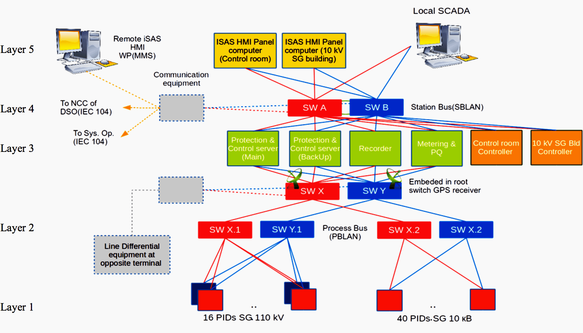
Software-based PAC System Architecture
The core of the designed PACS is the iSAS software suite that allows freedom to decide where and how to place a particular function. The iSAS is not dependent on hardware used and provides freedom to allocate function modules among available computation platforms.
Optimization research was performed to define the most suitable and effective system physical structure for this particular substation. An optimization procedure was used to gradually approach the desired values of system’s quality metrics, starting from the simplest and cheapest structure that provides system operability in required functionality using an iterative approach.
The simplest system means:
- No redundancy,
- Maximum functions concentration in single hardware,
- No periodical checking and testing, and
- No diagnostic.
At each next step of the optimization algorithm, one improvement measure is added. The improvement measure is chosen from the list that was ranked by cost efficiency. At the start, the measures with highest efficiency rating are used. PAC functions availability and maximum affordable repairing rate was applied as system’s quality metrics. Normative values of system metrics were taken from the conventional PAC system of the same substation.
The customer’s requirements, such as placing revenue metering and PQ functionality into a dedicated server with its separate cabinet, were taken into consideration. Optimization studies resulted in the system structure shown in Figure 1 above.
Reference // Centralized Substation Protection and Control – IEEE PES / Power System Relaying Committee (Report of Working Group K15 of the Substation Protection Subcommittee)