
Estimated Study Time: 13 minutes
Direct current as source of operating power
The 220V DC system supplies direct current as source of operating power for control, signaling, relays, tripping and closing of switchgears, emergency motors of most important auxiliary systems.
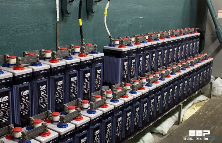
Under normal conditions of station generation, the storage battery units are kept floating in DC bus bars by means of the trickle chargers (also known as float chargers).
With this, the trickle charger besides meeting all the DC requirements of the power station, supplies a few hundred milliamps of direct current to the battery to compensate the loss in the capacity of the battery due to action between the plates of the cell.
With this arrangement, the battery remains connected to the DC bus bars as a standby supply source and immediately supplies the DC load in the vent of temporary failure of complete AC system.
The complete AC power system failure in a power station is known as emergency situation. DC battery units are designed to supply station DC loads for an emergency period of one hour. The tickle charger normally supplies the station DC load and the momentary loads will also be catered for by the trickle charger and if such a load is more than its capacity, the battery being in parallel with the trickle charger will supply the excessive load.
The trickle charger will normally be kept operating at around 115×2.15 V ie 247 volts. In case of AC mains failure the full battery of 115 cells will supply the load ie 230 volts. If the emergency lasts for one hour with an appropriate load of 450 Amps, then battery will supply the load for one hour when its end voltage will drop down to 1.75 volts per cell ie 201 volts.
After the emergency when the quick charger is closed the full battery will receive a boost charge and at the same time only the voltage of 98 cells will appear across the load.
If a second emergency occurs during quick charging, then immediately all the 115 cells are connected to the bus by closing the switch meant for the purpose. During routine daily testing of emergency DC motors connected to main distribution board middle section, supply has to be taken from the quick charger and the middle section has to be kept isolated from the left and right sections of main distribution board. This is to test the quick charger.
Types of battery being used:
- Lead-acid battery tubular
- Lead-acid battery plaint
- Ni-Cd battery
Battery commissioning
- The battery is charged initially to its capacity. The lead acid Battery has a capacity of 1000AH ie it may be charged for 10 hrs with charging current of 100 A or 5 hrs with charging current of 200 A. in case of Ni-Cd battery with a capacity of 2500 AH is charged for 12.5 hrs. with a charging current of 200A.
- Now the battery is discharged at the rate of 10% of its capacity in case of lead-acid battery and 20% or 40% of its capacity in case of Ni-Cd battery.
- Now the battery is recharged to its capacity.
- Constant voltage charging of battery is called float charging. A lead acid battery of cell voltage 2.2V is float charged upto 2.42 V. A Ni-Cd battery of cell voltage 1.2V is float charged upto 1.41 V.
- Constant current charging of a battery is called boost charging. A lead acid battery with bank voltage 237 may be boost charged to 279V. A Ni-Cd battery with bank voltage 242 may be boost charged to 283V.
Equipment used in 220V DC supply system
Sources of AC power
Two sources of AC power have been provided for both quick charger and trickle charger, one is the normal source and other is standby. AC power supply to the chargers is through transformers having off-load tap changing arrangement. An AC voltage-signaling relay communicates; ‘AC voltage low’ when the supply voltage becomes low.
Voltage level indicating device
A voltage level indicating device in MDB gives audio and visual annunciation when the DC bus voltage changes beyond set low (180-210) and high limits (240-270).
AVR
The DC voltage is maintained at desired value automatically by means of AVR unit provided at panel board.
Insulation monitoring device
This device annunciates when the insulation resistance of either positive bus to earth or negative bus to earth falls below 20 kilo ohms and also when the ratio of insulation resistance of positive bus to earth to negative bus to earth is 1.5 or above.
Flickering light device
This has been installed in the MDB, for flicker supply to control and check whether device is in order or not. Control and signaling panels have two sets of bus bars, one fed by main distribution board left section and the other by MDB right section.
The loads of the first panel should be kept switched to the set of bus bars fed by MDB. Left section and the loads of the second panel should be kept connected to the set of bus bars fed by MDB right section.
Electrostatic Precipitator
Dust extraction from industrial gases has become necessity for environmental reasons or for improving production. Most of the plants in India use coal as fuel for generating steam. The exhaust gases contain large amount of smoke and dust, which are being emitted into the atmosphere. This has posed a real threat to the mankind as a devastating health hazard. Hence it becomes necessary to free the exhaust from smoke and dust.
There are various ways of extracting dust. Electrostatic dust precipitation method is most widely used as its efficiency is excellent and it is easier to maintain.
Its other advantages are:
- Ability to treat large volumes of gases at high temperature
- Ability to cope up corrosive atmosphere
- Offer low resistance path for gas flow.
An electrostatic precipitator is equipment, which utilizes an intense electric force to separate suspended particles from the flue gases.
The process involves:
- Electrical charging of suspended particles
- Collection of charged particles from collecting electrode.
- Removal of particles from collecting electrode.
The flue gases pass between electrodes and are subjected to an intense electric field. The emissive electrodes are connected to the negative polarity of HV power supply while collecting electrodes are connected to positive polarity and grounded.
The HV power supply equipment is supplied in two parts:
- The high voltage transformer rectifier (HVR)
- The electronic controller (EC)
The EC-HVR equipment provides high voltage DC across the precipitator electrodes. The EC provides controlled AC voltage through thyristors (SCR) and associated controls to the primary of step up transformer. The EC has been designed to supply 0 to 415V to the primary of step up transformer through AC reactor. The equipment operates as constant current controller.
Heaters
Heaters are provided to raise the temperature of flue gases, as they become conductive when heated. 24 heaters are provided for stage I electrostatic precipitators. Rating: 550W heaters.
Zones
The flue gases from the boiler section reach electrostatic precipitator section through ducts. The flue gases are allowed to pass through various zones each having its own heaters, collecting and emissive electrodes and DC supply. These zones are provided to lessen the burden on a single zone and to take the load of other zone in case of maintenance or damage of a particular zone.
Stage I have 16 zones eight belonging to PASS A and rest to PASS B. Stage II has 20 Zones five belonging to each PASS A, PASS B, PASS C and PASS D.
Diodes
These are provided to rectify the AC voltage to the required DC voltage for electrostatic precipitators to work. The required DC voltage is 70 kV, 1000 mA. Type: BY 127
Motors
Rapping motors are provided along with each zone. A hammer is coupled to each of the motor’s shaft. Due to rotary motion of motor these hammers hit the collecting electrodes after a certain time delay and the ash is allowed to flow down through outlet in form of slurry. Rating: .5A motors
A GD screen (gas diverting) motor is also provided in electrostatic precipitator to provide a zigzag motion of flue gas so as to allow the heavy dust particles to settle down and removed.
Features:
Spark regulation
Flashovers of extremely low intensity are difficult to detect using the comparator technique. Non detection results in sustained arcing which may damage the collecting electrode. For such digital detection system is adopted.
Fast ramp control
In case of fast changes in operating conditions of precipitator many sparks may occur within a short time reducing current to a low value, when the disturbance disappears, it may take a relatively long time before the current can assume its normal value. This is the case particularly if selected rate of rise is low.
Modes of operation
Back corona mode
In this mode the precipitator voltage decreases with increase in precipitator current. This reduces the efficiency of precipitator and consumes unnecessary power.
Charge ratio mode
In a high resistive dust a potential gradient is created within the dust layers which causes occurrence of local sparks in dust layer. This spurious discharges or BACK CORONA occurs as soon as potential gradient is high. This has negative impact on efficiency.
Charge ratio
This mode supplies current in pulses and provides a dense corona for a short circuit time and at same time gives a low current to avoid back corona.
Reference // Internet and several books of Electrical Engineering
Related electrical guides & articles


Bipul Raman
Bipul Raman (@BipulRaman) is a Technology Enthusiast, Programmer and Blogger. Read more at : https://www.bipul.inProfile: Bipul Raman

I am working for thermal power plant .Is there any remedies to identify DC earth fault source at the earliest and take necessary action.
Witch battery parlour & series
please i want a catalogue for 150A,220V D.C output battery charger ( Nickel – Cadmium Pocket Plate Batteries ).
Please send me your email address so that I can send you the specifications of the 180 ampere batteries. It’s really urgent. Thanks.
dc-dc converters 220 to 48 & 110 to 48 for communication equipments in Ele .engg
Is there any training scheduled on 220 v dc battery and battery charger used in hydropwer wiithin india.