
It’s all about performance…
Performance requirements for various types of induction motors for use on standard sinewave power supplies are identified in NEMA MG1. Some of these types of motors are suitable for use in variable speed applications, dependent on the type of application.
Performance requirements are also identified for motors for specific use invariable speed applications.
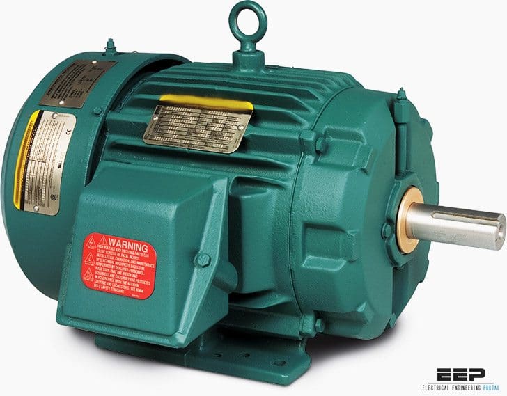
The purpose of this section is to provide guidance on the selection of one or more of the types of motors identified in NEMA MG1 that may be appropriate for the particular variable speed application under consideration. See Figure 1.

The turning force which a motor develops is known as torque. The amount of torque necessary to start a load (starting torque) is usually different from the torque required to keep the load moving (full load torque).
Loads which have a high breakaway friction or that require extra torque for acceleration, should have a motor specified to have high starting torque.
NEMA motor design A
NEMA MG1 does not impose any limits on the magnitude of the locked-rotor current on Design A motors, other than that the locked-rotor current is greater than the upper limit for Design B motors.
Such motors typically require the use of reduced voltage starting techniques for starting across the standard utility power source. However, normal adjustable frequency control function limits motor operation to the portion of its torque speed characteristic that lies between no-load and breakdown, even during starting.
Because of this, the higher locked rotor current of Design A motors is generally of little concern and the motors are well suited for variable speed operation, exhibiting low slip and high efficiency.
The potentially higher breakdown torque of a Design A motor will extend its constant horsepower speed range beyond that achievable by a Design B motor. However, caution should be used when applying Design A motors in by-pass operation, as their high locked-rotor current can increase starter, thermal overload, and short circuit protection device sizing.
Design A motors may also suffer greater thermal and mechanical stress thanother designs when started across-the-line. Design A motors with very low slip may also exhibit instability under lightly loaded conditions.
NEMA motor design B
Design B motors are applied in variable torque, constant torque and constant horsepower applications.
Adjustable frequency control algorithms are generally optimized to the speed-torque-current characteristics of Design B motors. They exhibit good efficiency and low slip,and are suitable for across-the-line starting in bypass mode.
Design B motors with very low slip may also exhibit instability under lightly loaded conditions.
NEMA motor design C
Design C motor speed-torque-current characteristics were defined to address across-the-line applications requiring high starting(locked-rotor) torque while generally maintaining Design Blocked-rotor current, but slightly higher slip.
Since a Design B motor operated from an adjustable frequency control can provide the same breakaway torque as a Design C motor operated from a control, it is usually preferred because of its industry-standard availability and higher running efficiency. Also, since an adjustable frequency control driven motor normally operates at speeds above the breakdown speed, the high locked-rotor and pull-up torque of a Design C motor serves no benefit in most adjustable speed drive applications.
This can result in additional heating in Design C motors over that in Design B and a corresponding greater decrease in system efficiency. Design B motors may not be suitable for bypass operation in an application that normally requires use of a Design C motor for fixed frequency application.
NEMA motor design D
Design D motors were developed specifically for high impact, high starting torque, or high inertia loads.
They exhibit very high locked-rotor torque but suffer in running efficiency due to their high slip characteristic. By employing negative slip compensation with an adjustable frequency control, a Design A, B or C motor can be made to emulate the speed-torque characteristic of a Design D motor while providing higher running efficiency.
Design A, B, or C motors cannot be used for bypass operation on an application that normally requires a Design D motor for fixed frequency application.
References
- NEMA Standards Publication – Application Guide for AC Adjustable Speed Drive Systems
- BALDOR (A member of the ABB Group) – Specifier Guide


درخصوص چگونگی سردکردن موتورهای سرعت متغیر که توان بالایی دارند نیز به این موضوع افزوده شود
Pleas attached cooling method for variable motor speed that have power greather than 100 KW.