
Estimated Study Time: 15 minutes
Non-linear loads
Harmonic load currents are generated by all non-linear loads. This includes:
- Switched mode power supplies (SMPS)
- Electronic fluorescent lighting ballasts
- Variable speed drives (VSDs)
- Uninterruptible power supplies (UPS)
- Magnetic-cored devices

1. Switched mode power supplies (SMPS)
The majority of modern electronic units use switched mode power supplies (SMPS).

These differ from older units in that the traditional step-down transformer and rectifier is replaced by direct controlled rectification of the supply to charge a reservoir capacitor from which the required direct current is derived by a method appropriate to the output voltage and current required.
The advantage – to the equipment manufacturer – is that the size, cost and weight is significantly reduced and the power unit can be made in almost any required form factor.
The disadvantage – to everyone else – is that, rather than drawing continuous current from the supply, the power supply unit draws pulses of current which contain large amounts of third and higher harmonics and significant high frequency components.
For high power units there has been a recent trend towards so-called power factor corrected inputs. The aim is to make the power supply load look like a resistive load so that the input current appears sinusoidal and in phase with the applied voltage. It is achieved by drawing input current as a high frequency triangular waveform that is averaged by the input filter to a sinusoid.
This extra level of sophistication is not yet readily applicable to the low-cost units that make up most of the load in commercial and industrial installations.
2. Fluorescent lighting ballasts

Electronic lighting ballasts have become popular in recent years following claims for improved efficiency. Overall they are only a little more efficient than the best magnetic ballasts and in fact, most of the gain is attributable to the lamp being more efficient when driven at high frequency rather than to the electronic ballast itself.
Power-factor corrected types are becoming available which reduce the harmonic problems, but at a significant cost penalty.

Magnetic ballasts also generate harmonics but levels are generally lower than those produced by electronic units. They often incorporate a local power factor correction capacitor which act as a low impedance shunt for the harmonic currents. Consequently, the level of distortion that propagates into the distribution system is lower and fewer problems arise.
3. Variable speed DC drives

Variable speed controllers for DC motors are usually based on the three-phase bridge, which is also used in D.C. transmission links and uninterruptible power supplies. It is also known as the six-pulse bridge because there are six pulses per cycle (one per half cycle per phase) on the D.C. output.

The current is described by the series:

The bridge will therefore produce harmonics of the order:
n = 6k ± 1 where k is an integer
and the magnitude of each harmonic current will be:
In = I1 / n where I1 is the 50 Hz component.
These equations are valid only when the source impedance is low and the supply voltage is a pure sinusoid. In theory, the controller produces 30% total harmonic currents distributed as follows:
Table 1 – figures for harmonic current distortion
| Harmonic number | 5 | 7 | 11 | 13 | 17 | 19 | 23 | 25 |
| Magnitude (%) | 20.0 | 14.3 | 9.1 | 7.7 | 5.9 | 5.3 | 4.3 | 4.0 |
In practice, DC motors have finite inductance, so there is a 300 Hz ripple (i.e. six times the supply frequency) on the DC current. This changes the harmonic profile of the supply current and fifth harmonic currents of up to 50% have been encountered with some motors.
There is a trend towards using motors with lower inductance to reduce cost, but this can prove to be a false economy; the higher levels of harmonics are more difficult to deal with and harmonic filters, often designed for the theoretical case, may be damaged.
The magnitude of the harmonics 5, 6 is significantly reduced by the use of a twelve-pulse bridge. This is effectively two six-pulse bridges, fed from a star and a delta transformer winding, providing a 30 degrees phase shift between them. The fifth and seventh harmonics are theoretically removed, but in practice, they are only reduced by a factor between 20 and 50.
The higher harmonics remain unchanged, reducing the total harmonic current to about 12%, again assuming zero source impedance. Not only is the total harmonic current reduced, but also those that remain are of a higher order making the design of the filter much easier.
Further increase in the number of pulses to 24, achieved by using two parallel twelve-pulse units with a phase shift of 15 degrees, reduces the total harmonic current to about 4.5%. The extra sophistication increases cost of course, so this type of controller would be used only when necessary to comply with the electricity suppliers’ limits.
The figures for harmonic current distortion given above assume that the source impedance is zero. If it were, the level of harmonics would be irrelevant because no voltage distortion would result and other consumers would not be affected. In reality, the source impedance is finite (see Table 1) and, under these conditions, the current distortion is considerably reduced.
Of course, since the distorted current is flowing through the source impedance, voltage distortion results.

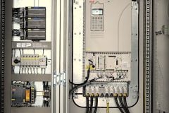
Variable speed controllers for AC motors use similar converters to produce DC followed by an inverter to produce AC at the required frequency for the drive. As well as the harmonics that would be expected for the converter, other components of current are produced which are related to the operating speed of the drive.
The harmonic current profile is dependent on the precise design of the converter and inverter. Because of the large size of drives of this type, local filtering is normally provided but the design of filters for these systems is often very difficult.
4. Uninterruptible power supplies (UPS)
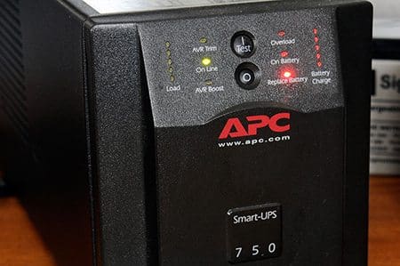
UPS are available in many different forms depending on how the power conversion is achieved and how the change over from external to internal supply takes place. Most units up to a few MVA use solid state inverters (termed static) to generate the output power, very large units use motor generators (rotary).
Typical configurations include:
On-line UPS //
An on-line UPS converts AC line power to DC to keep a battery charged and inverts DC battery power to produce AC. The load is continuously fed from the constant battery power, regardless of supply conditions.
Because the whole of the supply is converted twice, this type of UPS is relatively inefficient and is used only for small units.
Off-line UPS //
An off-line UPS feeds the load from the mains supply when it is available. The inverter/converter is normally inactive until a disruption occurs, when the battery delivers power to the inverter, which converts the DC power back to AC power for the load.
The drawback is that the time needed to transfer from AC to battery can present a problem for some sensitive equipment such as computers and servers.
Line-interactive technology //
A line-interactive design combines the characteristics of on-line and off-line designs. The inverter in this design performs a dual function. Under normal operation, it keeps the battery fully charged. When a power supply failure is detected, the inverter is disconnected from the supply and power is provided from the battery through the inverter to the load.
Similar to an off- line UPS, line-interactive technology is efficient because power is normally supplied directly from the line. Heat and stresses are minimised because the line-interactive UPS delivers only incremental power, compensating for line voltage sags via the output transformer. Like the on- line UPS, it also provides continuous power.
The input converter of a UPS is very similar to that for the variable speed drive discussed above and results in similar harmonic distortion.
During normal operation the off-line and line interactive designs draw a relatively low input current, having only to maintain the battery charge, but the installation design must take account of the effect of the full load current which will flow when recovering from a blackout.
How a UPS Works? (VIDEO)
Cant see this video? Click here to watch it on Youtube.
The load on the output of the UPS is invariably composed of IT equipment and is therefore non- linear and rich in low order harmonics. The output transformer of the UPS must be adequately rated to cope with the excess heating that will result.
In three-phase systems the ‘triple-N’ harmonics (i.e. harmonics which are an odd multiple of three) add in the neutral. All neutral conductors within the UPS and in the rest of the distribution circuit should be adequately rated to carry these increased currents, which can approach twice the phase current.
When specifying a UPS care should be taken to ensure that the true nature of the load is understood and properly communicated to the supplier.
5. Magnetic cored devices
The relationship between the magnetising current and the resulting flux density in an inductor with a magnetic core is inherently non-linear. If the current waveform is constrained to be sinusoidal, i.e. the series resistance in the circuit is high, then the magnetic field will contain harmonics.
Transformers typically introduce a small amount of voltage distortion, about 1.5%, into the output waveform.
Fluorescent light fittings using chokes generate some harmonics due to the non-linear behaviour of the lamp itself (it has a negative dynamic resistance) and the non-linear behaviour of the core. Levels are generally lower than those produced by electronic ballasts.

Reference // A Good Practice Guide to Electrical Design – Copper Development Association (download here)
Related electrical guides & articles


Edvard Csanyi
Hi, I'm an electrical engineer, programmer and founder of EEP - Electrical Engineering Portal. I worked twelve years at Schneider Electric in the position of technical support for low- and medium-voltage projects and the design of busbar trunking systems.I'm highly specialized in the design of LV/MV switchgear and low-voltage, high-power busbar trunking (<6300A) in substations, commercial buildings and industry facilities. I'm also a professional in AutoCAD programming.
Profile: Edvard Csanyi

First of all thanks for sharing a knowledgeable topics… But there was problem.. Much ads… And the question are not open full…some thing payment… Etc.. Some people are not afford to pay.. Amount… I requested to open for all…soo all the students are easy use the important notes..
This is a good job.The information here is valuable.
I have to admit that Edvard is one of the best editor and always participate with his wide knowledge. It is pleasure to read Edvard :-)
I respect Electrical Engg. and this site makes me feel good..thanks for the Article?
You’re welcome Chandan, thanks for stepping by and reading!
Dear Sir,
Really I am appreciate what you have written here & what information are you feeding us.
good blase you.
The Article presented here is very useful for my new engineer as a reference to excel his knowledge on electrical engineering subject. Two thumbs up.
I can not download articlesusing the android application. Pleas update application to solve this problem
One of the main source of harmonics is power rectifiers, which can be found in railway and subway substations and in metal industry.