
Estimated Study Time: 12 minutes
Dimensioning & network calculation
Basically, the dimensioning process itself is easy to understand and can be performed using simple means. Its complexity lies in the procurement of the technical data on products and systems, which can be found in various technical standards and regulations on the one hand and numerous product catalogues on the other.
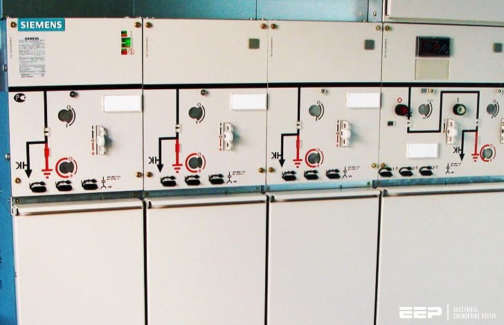 9 basic rules for dimensioning of electric circuits (on photo: SIEMENS 24kV medium voltage switchgear type 8DJH; credit: smartenergo.net)
An important aspect in this context is the cross-circuit manipulation of dimensioned components owing to their technical data, for example, the below mentioned inheritance of minimum current breaking times of the non-stationary load circuit to other stationary load or distribution circuits.
Complexity is further increased by country-specific standards, regulations, and different installation practices applying to the two dimensioning areas. For reasons of risk minimisation and time efficiency, a number of engineering companies generally use advanced calculation software (such as SIMARIS design) to perform dimensioning and verification processes in electrical power systems.
The following nine basic dimensioning rules and standards principally apply to all circuit types //
- Supply circuits
- Distribution circuit
- Rated current rule
- Tripping current rule
- Short-circuit energy
- Short-circuit time
- Final circuits
- Permissible voltage drop
- Protection against electric shock
1. Supply circuits
Particularly high requirements apply to the dimensioning of supply circuits. This starts with the rating of the power sources. Power sources are rated according to the maximum load current to be expected for the power system, the desired amount of reserve power, and the degree of supply reliability required in case of a fault (overload / short circuit).
Reserve power and operational safety in the vicinity of the supply system are usually established by building up appropriate redundancies, for example by //
- Providing additional power sources (transformer, generator, UPS)
- Rating the power sources according to the failure principle, n- or (n-1) redundancy: applying the (n–1) principle means that two out of three supply units are principally capable of continually supplying the total load for the power system without any trouble if one power source fails
- Rating those power sources that can temporarily be operated under overload (for example using vented transformers)
Independent of the load currents established, dimensioning of any further component in a supply circuit is oriented to the ratings of the power sources, the system operating modes configured and all the related switching states in the vicinity of the supply system.
As a rule, switching / protective devices must be selected in such a way that the planned power maximum can be transferred. In addition, the different minimum / maximum short-circuit current conditions in the vicinity of the supply system, which are dependent on the switching status, must be determined.
When connecting lines are rated (cable or busbar trunking system), appropriate reduction factors must be taken into account, which depend on the number of systems laid in parallel and the installation type.
When devices are rated, special attention should be paid to their rated short-circuit breaking capacity. You should also opt for a suitable switch (air circuit-breaker or moulded-case circuit-breaker) with a high-quality tripping unit and variable settings, as this component is an important basis for attaining the best possible selectivity towards all upstream and downstream devices.
Go back to Dimensioning Rules ↑
2. Distribution circuit
Dimensioning of cable routes and devices follows the maximum load currents to be expected at this distribution level.
As a rule:
Ibmax = Σ installed capacity · simultaneity factor
Switching / protective device and connecting line are to be matched with regard to overload and short-circuit protection. In order to ensure overload protection, you must also observe the standardised conventional (non-)tripping currents referring to the device applied.
Go back to Dimensioning Rules ↑
The following basic rules must be observed to ensure overload protection //
3. Rated current rule
Non-adjustable protective equipment //
IB ≤ In ≤ Iz
The nominal current In of the selected device must be in between the established maximum load current IB and the maximum permissible load current Iz of the selected transmission medium (cable or busbar trunking system).
Adjustable protective equipment //
IB ≤ Ir ≤ Iz
The setting value of the overload tripping unit Ir of the selected device must be in between the established maximum load current IB and the maximum permissible load current Iz of the selected transmission medium.
Go back to Dimensioning Rules ↑
4. Tripping current rule
I2 ≤ 1.45 · Iz
The maximum permissible load current Iz of the selected transmission medium must be above the high test current I2/1.45 of the selected device. The high test current I2 is standardised and varies according to type and characteristics of the protective equipment applied.
Go back to Dimensioning Rules ↑
The following basic rules must be observed to ensure short-circuit protection //
5. Short-circuit energy
K2S2 ≥ I2t
(K = material coefficient; S = cross section)
The amount of energy that is set free from the moment when a short circuit occurs, until it is cleared automatically, must at any time be less than the energy which the transmission medium can carry as a maximum before irrepairable damage is caused.
According to IEC 60364-4-43 (VDE 0100-430) this basic rule is valid up to a time range of max. 5 s. Below a short-circuit clearing time of 100 ms, the let-through energy of the protective device must be factored in (see device manufacturer data).
Go back to Dimensioning Rules ↑
6. Short-circuit time
ta (Ikmin) ≤ 5 s
The resulting current breaking time of the selected protective equipment must ensure that the calculated minimum short-circuit current Ikmin at the end of the transmission line or protected line is automatically cleared within 5 s at the latest.
Overload and short-circuit protection needn’t necessarily be provided by one and the same device. If required, these two protection targets may be accomplished by a device combination.
The use of separate switching / protective devices could also be considered, i.e. at the start and end of a cable route. As a rule, devices applied at the end of a cable route can ensure overload protection for this line only.
Go back to Dimensioning Rules ↑
7. Final circuits
The method for coordinating overload and short-circuit protection is practically identical for distribution and final circuits. Besides overload and short-circuit protection, the protection of human life is also important for all circuits.
Go back to Dimensioning Rules ↑
8. Permissible voltage drop
For cable dimensioning, the maximum permissible voltage drop must be factored in. This means that the chain: voltage drop – cable diameter – bending radiuses – space requirements also influences the room size and costs to be taken into account for planning.
Go back to Dimensioning Rules ↑
9. Protection against electric shock
ta (Ik1 min)≤ ta perm.
If a 1-phase fault to earth (Ik1 min) occurs, the resulting current breaking time ta for the selected protective equipment must be shorter than the maximum permissible breaking time ta perm. which is required for this circuit according to IEC 60364-4-41 (VDE 0100-410) to ensure the protection of persons.
As the required maximum current breaking time varies according to the nominal line voltage and the type of load connected (stationary and nonstationary loads), protection requirements regarding minimum breaking times ta perm. may be transferred from one load circuit to other circuits. Alternatively, this protection target may also be achieved by observing a maximum touch voltage.

Depending on the power supply system, the defined protection must be built up as shown in Figure 1 above.
As final circuits are often characterized by long supply lines, their dimensioning is often greatly influenced by the maximum permissible voltage drop. As far as the choice of switching / protective devices is concerned, it is important to bear in mind that long connecting lines are characterized by high impedances and thus strong attenuation of the calculated short-circuit currents.
Depending on the system operating mode (coupling open, coupling closed) and the medium of supply (transformer or generator), the protective equipment and its settings must be configured for the worst case concerning short-circuit currents. In contrast to supply or distribution circuits where a high emphasis is placed on the selection of a high-quality tripping unit, final circuits are satisfied with a tripping unit in LI characteristic for overload and instantaneous shortcircuit protection.
Go back to Dimensioning Rules ↑
Reference // Planning of Electric Power Distribution – Technical Principles // SIEMENS
Related electrical guides & articles


Edvard Csanyi
Hi, I'm an electrical engineer, programmer and founder of EEP - Electrical Engineering Portal. I worked twelve years at Schneider Electric in the position of technical support for low- and medium-voltage projects and the design of busbar trunking systems.I'm highly specialized in the design of LV/MV switchgear and low-voltage, high-power busbar trunking (<6300A) in substations, commercial buildings and industry facilities. I'm also a professional in AutoCAD programming.
Profile: Edvard Csanyi

Dear Edvard,I wants to know how we get the values of In,Ib,Iz,Ir,S,k,ta for the design.Is it obtained from the manufacturer’s catalogue?
THESE ARE GOOD STUFF ON ELECTRICAL POWER SYSTEM.
can you explain full operation of ACB & VCB.AND how to maintenance of above,the breaker,3
Can u explain about Electrostatic precipitator,their function and basically problem at esp and how to solve