Every electric motor has operating limits. Overshooting these limits will eventually destroy it and the systems it drives, the immediate effect being operating shutdown and losses. A short circuit is a direct contact between two points of different electric potential:
– Alternating current: phase-to-phase contact, phase-to-neutral contact, phase-to-ground contact or contact between windings in a phase,
– Direct current: contact between two poles or between the ground and the pole insulated from it.
This can have a number of causes: damage to the varnish insulating the conductors, loose, broken or stripped wires or cables, metal foreign bodies, conducting deposits (dust, moisture, etc.).
A short circuit results in a sudden surge of current which can reach several hundred times the working current within milliseconds. A short circuit can have devastating effects and severely damage equipment. It is typified by two phenomena.
Thermal phenomenon
A thermal phenomenon corresponding to the energy released into the electrical circuit crossed by the short circuit current I for at time t based on the formula I2t and expressed as A2s. This thermal effect can cause:
- Melting of the conductor contacts,
- Destruction of the thermal elements in a bimetal relay if coordination is type 1,
- Generation of electrical arcs,
- Calcination of insulating material,
- Fire in the equipment.
Electrodynamic phenomenon
An electrodynamic phenomenon between conductors producing intensive mechanical stress as the current crosses and causing:
- Distortion of conductors forming the motor windings,
- Breakage of the conductors’ insulating supports,
- Repulsion of the contacts (inside the contactors) likely to melt and weld them.
These results are dangerous to property and people. It is therefore imperative to guard against short circuits with protection devices that can detect faults and interrupt the short circuit rapidly, before the current reaches its maximum value.
Two protection devices are commonly used for this:
- Fuses, which break the circuit by melting and must be replaced afterwards,
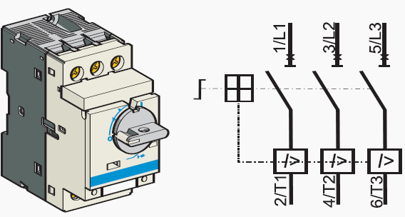
- Magnetic circuit breakers which automatically break the circuit and only require to be reset.
Short-circuit protection can also be built into multifunction devices such as motor starter protection and contactor breakers.
Definitions and characteristics
The main characteristics of short-circuit protection devices are:
- Breaking capacity: the highest value in the estimated short-circuit current that a protection device can break at a given voltage,
- Closing capacity: the highest value a protection device can reach at its rated voltage in specified conditions. The closing value is k times the break capacity as shown in the table below.
| Break capacity (BC) | φ Cos | Closing capacity (CC) |
| 4.5kA < BC < 6kA | 0.7 | 1.5 BC |
| 6kA < BC < 10kA | 0.5 | 1.7 BC |
| 10kA < BC < 20kA | 0.3 | 2 BC |
| 20kA < BC < 50kA | 0.25 | 2.1 BC |
| 50kA < BC | 0.2 | 2.2 BC |
Break and closing capacities for circuit breakers by the IEC 60947-2 standard
Fuses
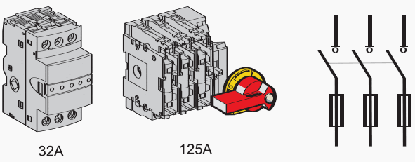
Fuses perform phase-by-phase (single pole) protection with a high break capacity at low volume. They limit I2t and electrodynamic stress (Icrête).
They are mounted:
- On special supports called fuseholders,
- Or on isolators in the place of sockets and links.

Note that trip indicator fuse cartridges can be wired to an all-pole switching device (usually the motor control contactor) to prevent singlephase operation when they melt.
The fuses used for motor protection are specific in that they let through the overcurrents due to the magnetising current when motors are switched on. They are not suitable for protection against overload (unlike gG fuses) so an overload relay must be added to the motor power supply circuit. In general, their size should be just above the full load current of the motor.
Magnetic circuit breakers

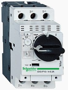
These circuit breakers protect plant from short circuits within the limits of their breaking capacity and by means of magnetic triggers (one per phase). Magnetic circuit breaking is all-pole from the outset: one magnetic trigger will simultaneously open all the poles.
For low short-circuit currents, circuit breakers work faster than fuses. This protection complies with the IEC 60947-2 standard. To break a short-circuit current properly, there are three imperatives:
- Early detection of the faulty current,
- Rapid separation of the contacts,
- Breakage of the short-circuit current.
Most magnetic circuit breakers for motor protection are current-limiting devices and so contribute to coordination (C Fig.52). Their very short cut-off time breaks the short-circuit current before it reaches its maximum amplitude.
This limits the thermal and electrodynamic effects and improves the protection of wiring and equipment.


Good article , but , By the way , I would understand that for low voltage protective device , Fuse would probably work faster than circuit breaker since it can trip less than 1/2 cycle (
(<10 ms for 50Hz network ) which could cause the short circuit peak current not reach to the maximum level that it could be , Consequently , The short circuit in term of RMS. is definitely be reduced . This technique is often called "current – limited or energy limit " .
On the contrary , comparison with circuit breaker , which normally have a tripping time for instantaneous mode of 30ms – 80ms ( more than 1/2 cycle ) depend on circuit breaker 's manufacturer.
However , please feedback or advice through my website if my understanding is not correct.
Thank you in advance :)