
Estimated Study Time: 6 minutes
Introduction
An electromechanical relay is an electrical switch actuated by an electromagnet coil. As switching devices, they exhibit simple “on” and “off” behavior with no intermediate states.
The electronic schematic symbol for a simple single-pole, single-throw (SPST) relay is shown here:
")
A coil of wire wrapped around a laminated iron core provides the magnetic field necessary to actuate the switch mechanism. This particular relay is equipped with normally open (NO) switch contacts, which means the switch will be in the open (off) state when the relay coil is de-energized.
A single-pole, single-throw relay with a normally-closed (NC) switch contact would be represented in an electronic schematic like this:
")
In the electrical control world, the labels “Form-A” and “Form-B” are synonymous with “normally open” and “normally closed” contact status. Thus, we could have labeled the SPST relay contacts as “Form-A” and “Form-B,” respectively:
")
An extension of this theme is the single-pole, double-throw (SPDT) relay contact, otherwise known as a “Form-C” contact. This design of switch provides both a normally-open and normally closed contact set in one unit, actuated by the electromagnet coil:
")
A further extension on this theme is the double-pole, double-throw (DPDT) relay contact. This design of switch provides two sets of Form-C contacts in one unit, simultaneously actuated by the electromagnet coil:

DPDT relays are some of the most common found in industry, due to their versatility. Each Form-C contact set offers a choice of either normally-open or normally-closed contacts, and the two sets (two “poles”) are electrically isolated from each other so they may be used in different circuits.
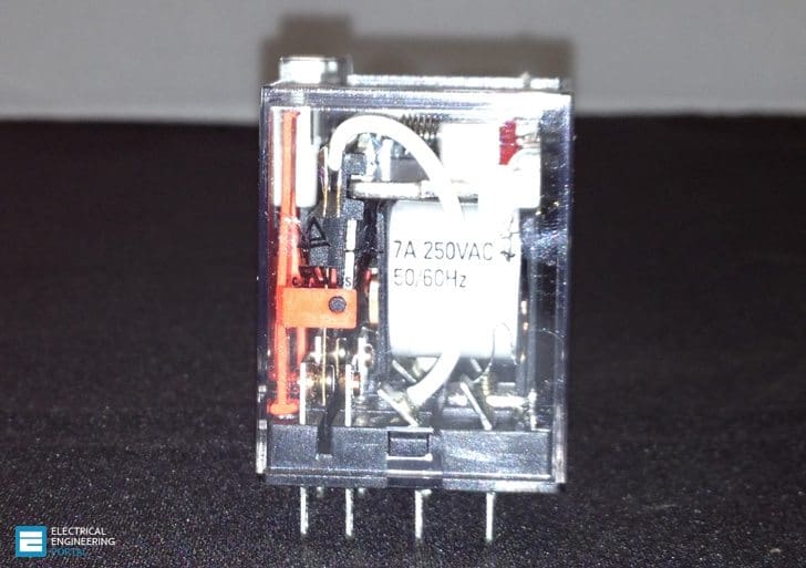
A DPDT “ice cube” relay is shown in the following photographs, ready to be plugged into its base (left) and with the plastic cover removed to expose both sets of Form-C contacts (right):

These relays connect to the socket with eight pins: three for each of the two Form-C contact set, plus two more pins for the coil connections. Due to the pin count (8), this style of relay base is often referred to as an octal base.
A closer view of one Form-C contact shows how the moving metal “leaf ” contacts one of two stationary points, the actual point of contact being made by a silver-coated “button” at the end of the leaf. The following photographs show one Form-C contact in both positions:

Industrial control relays usually have connection diagrams drawn somewhere on the outer shell to indicate which pins connect to which elements inside the relay.
The style of these diagrams may vary somewhat, even between relays of identical function. Take for instance the diagrams shown here, photographed on three different brands of DPDT relay:

Bear in mind that these three relays are identical in their essential function (DPDT switching), despite differences in physical size and contact ratings (voltage and current capacities). Only two of the three diagrams shown use the same symbols to represent contacts, and all three use unique symbols to represent the coil.
Reference: Lessons In Industrial Instrumentation by Tony R. Kuphaldt
Related electrical guides & articles


Edvard Csanyi
Hi, I'm an electrical engineer, programmer and founder of EEP - Electrical Engineering Portal. I worked twelve years at Schneider Electric in the position of technical support for low- and medium-voltage projects and the design of busbar trunking systems.I'm highly specialized in the design of LV/MV switchgear and low-voltage, high-power busbar trunking (<6300A) in substations, commercial buildings and industry facilities. I'm also a professional in AutoCAD programming.
Profile: Edvard Csanyi

Dear Sir,
I would like to order the Ice Cube Plus, please kindly advise where/how I can order this products.
Best regards,
Amnat