
Estimated Study Time: 9 minutes
Network automation for rural areas
The challenges in network automation for rural areas are similar to those in urban areas, however the network topology may be very different.
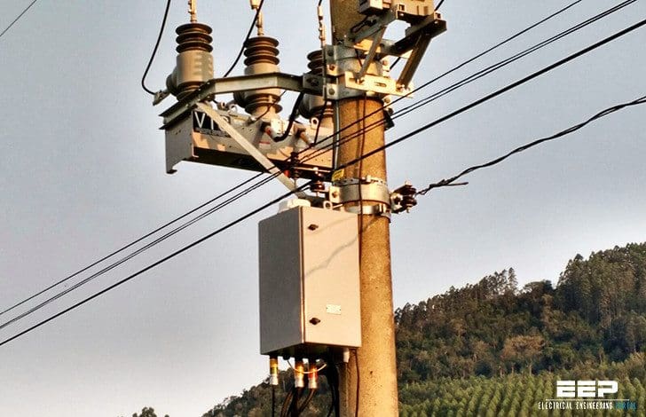 Automation of secondary distribution networks in rural areas (photo credit: orbcomm.com)
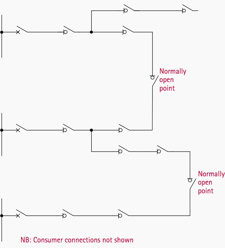
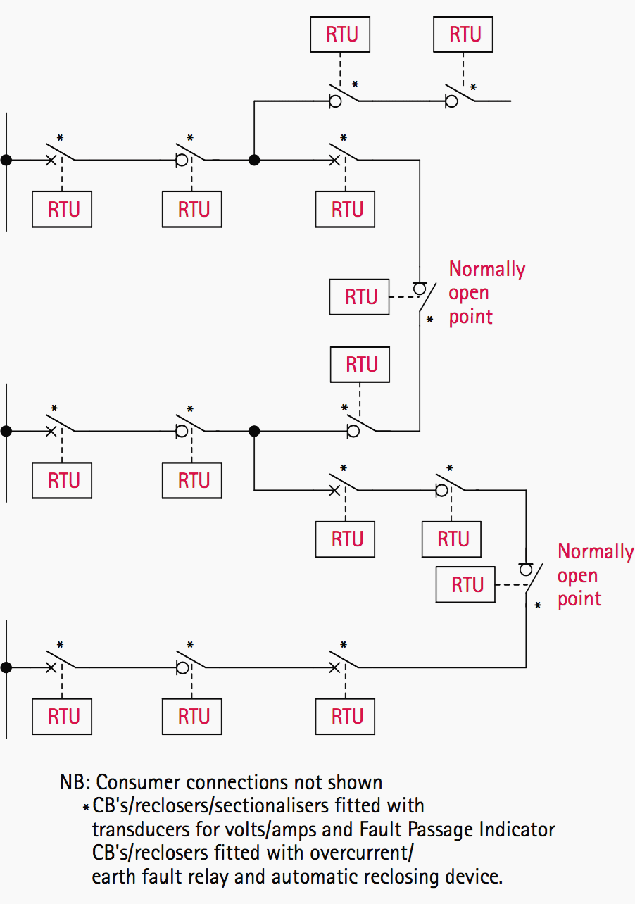
A typical conventional network topology is shown in Figure 1.
Due to relatively sparse population, feeders are generally radial, often with spur lines, and can be quite lengthy – 60km length of main feeder at 11kV being possible. The feeders are usually conventional overhead lines with uninsulated conductors, and fault rates for these lines are high in comparison with cables or EHV overhead lines.
In some countries, lightly insulated conductors are used, and these reduce the fault rates experienced.
Response times for location and repair of faults may be lengthy, as the only indication of a fault having occurred may be customer complaints of loss of supply due to the source circuit breaker having tripped. In this case, all consumers fed by the line will suffer loss of supply, and determining the location of the fault may take a considerable time.
Many possible enhancements taking advantage of automation techniques to the basic feeder topology are possible to improve the situation:
1. Circuit Breaker Remote Control/Monitoring
This provides a small advantage in alerting the operator to a loss of supply, and a larger one in minimizing restoration time. Most OHL faults are transient in nature, and therefore circuit breaker reclosure after a short time interval is likely to result in supply being restored. The operator may therefore attempt a manual closure of the circuit breaker to restore supply.
Use of an auto-reclose scheme may further reduce the disconnection time and relieve the control room operator of workload, especially in conditions of poor weather when many distribution feeders may suffer transient faults.

2. Automatic Sectionalizers
An automatic sectionalizer is a switching device that detects the flow of current in excess of a set value and opens a switch to disconnect the network downstream of the device.
Because such devices are usually pole-mounted, in locations remote from a suitable electricity supply, the sensing and switching mechanism is arranged to be self-powered. The expense of a transformer, etc. to provide such a supply from the supply side of the line is not justified and adds additional complication.
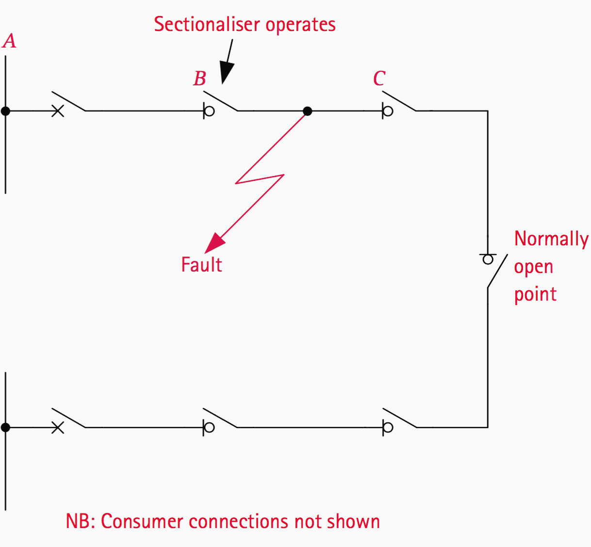
For circuits that have more than one feed and a normally open point (Figure 3), loss of supply until the fault is repaired can be limited to the section in which the fault lies.
The sectionalizer at point B opens automatically and the operator can take action to open the one at point C. The faulted section is thus isolated and (subject to system conditions being satisfactory) the sectionalizer at the normally open point may be closed.
Drawbacks
However, there can be drawbacks as well. Grading of the feeder circuit breaker with the sectionalizers may be difficult and result in longer fault clearance times for faults in the section between the circuit breaker and first sectionalizer. The circuit breaker must be rated for the resulting fault duty.
Consumers situated in healthy sections of line may suffer extended voltage dips, which may give rise to problems with equipment.
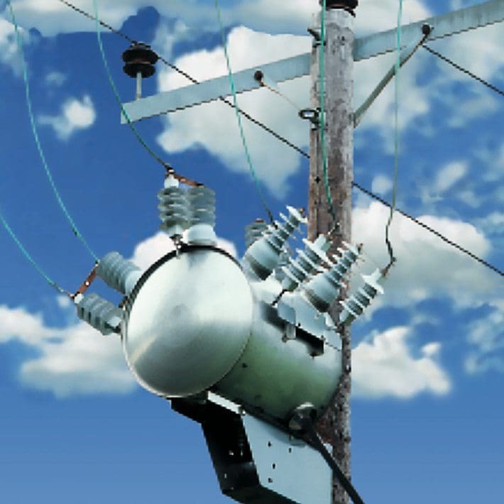
An illustration of the device is given in Figure 4 below.
It can be thought of as the distribution network equivalent to an auto-reclose scheme applied to circuit breakers on an EHV transmission line. It overcomes the disadvantage of a sectionalizer in that transient faults do not result in loss of supply to consumers downstream of the device.
How recloser works?
The first automatic reclosure operates a short time after opening and will usually be successful if the fault is a transient one. Should a fault still be detected upon the first reclosure, the recloser deliberately remains closed for a significant time to try and clear the fault by using the arc energy to burn out the cause of the fault. The recloser then opens, and closes after a pre-set dead time. Should the fault still exist, a further burn time/open/reclose cycle is carried out, after which a final open/lockout operation is performed if the fault still exists.
Figure 5 shows the distribution network of Figure 1 after application of full automation as described above.
The benefits provided are:
- Rapid restoration of supply to all consumers following transient faults
- Disconnection of the minimum number of consumers following a permanent fault
- Indication of network performance to the control centre, including fault location and network loading
- Reduced requirement of field crews to carry out manual switching
- Reduced fault location time
With existing equipment, such information may not be available at all unless a field measurement exercise is undertaken. The information can be used not only to identify constraints in the network, but also to determine spare capacity much more accurately (in terms of permissible short-term overloads possible without excessive temperature rises occurring).
Network re-inforcement may then possibly be postponed or even eliminated, resulting in reduced capital expenditure requirements. There is also the potential for improved thermal modeling of plant, to produce a more accurate thermal loss-of life indication.
How to operate recloser? (VIDEO)
Learn how to operate a recloser both manually and using the smart control panel.
Reference // Network protection and automation guide by Alstom
Related electrical guides & articles


Edvard Csanyi
Hi, I'm an electrical engineer, programmer and founder of EEP - Electrical Engineering Portal. I worked twelve years at Schneider Electric in the position of technical support for low- and medium-voltage projects and the design of busbar trunking systems.I'm highly specialized in the design of LV/MV switchgear and low-voltage, high-power busbar trunking (<6300A) in substations, commercial buildings and industry facilities. I'm also a professional in AutoCAD programming.
Profile: Edvard Csanyi
