Electrical parameters
In this technical article, you should gain a basic understanding of the desirable properties of practical devices for the measurement of electrical parameters. The measurements most often of interest are those of current, voltage, power, and resistance.

In analogy with the models we have just developed to describe the non-ideal behavior of voltage and current sources, we similarly present circuit models for practical measuring devices (instruments) suitable for describing the non-ideal properties of these devices.
The Ohmmeter
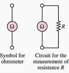
The ohmmeter is a device that when connected across a circuit element, can measure the resistance of the element. Figure 1 depicts the circuit connection of an ohmmeter to a resistor. One important rule needs to be remembered:
The resistance of an element can be measured only when the element is disconnected from any other circuit.


Go back to Measuring Devices ↑
The Ammeter
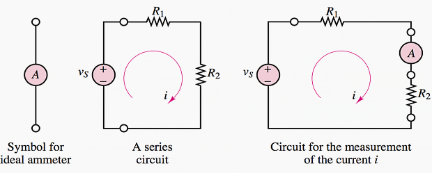
The ammeter is a device that when connected in series with a circuit element, can measure the current flowing through the element. Figure 2 illustrates this idea.
From Figure 2, two requirements are evident for obtaining a correct measurement of current:
- The ammeter must be placed in series with the element whose current is to be measured (e.g., resistor R2)
- The ammeter should not restrict the flow of current (i.e., cause a voltage drop), or else it will not be measuring the true current flowing in the circuit. An ideal ammeter has zero internal resistance.


Go back to Measuring Devices ↑
The Voltmeter
The voltmeter is a device that can measure the voltage across a circuit element. Since voltage is the difference in potential between two points in a circuit, the voltmeter needs to be connected across the element whose voltage we wish to measure.
A voltmeter must also fulfill two requirements:
- The voltmeter must be placed in parallel with the element whose voltage it is measuring.
- The voltmeter should draw no current away from the element whose voltage it is measuring, or else it will not be measuring the true voltage across that element. Thus, an ideal voltmeter has infinite internal resistance.


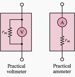
Once again, the definitions just stated for the ideal voltmeter and ammeter need to be augmented by considering the practical limitations of the devices. A practical ammeter will contribute some series resistance to the circuit in which it is measuring current.
Figure 4 depicts the circuit models for the practical ammeter and voltmeter.


Go back to Measuring Devices ↑
The Wattmeter
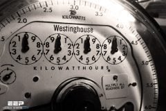
All the considerations that pertain to practical ammeters and voltmeters can be applied to the operation of a wattmeter, an instrument that provides a measurement of the power dissipated by a circuit element, since the wattmeter is in effect made up of a combination of a voltmeter and an ammeter. Figure 5 depicts the typical connection of a wattmeter in the same series circuit used in the preceding paragraphs.
In effect, the wattmeter measures the current flowing through the load and, simultaneously, the voltage across it and multiplies the two to provide a reading of the power dissipated by the load.


The objective of this article was to introduce the background needed successfull understanding of the further analysis of linear resistive circuits.
Go back to Measuring Devices ↑
Reference // Textbook of Electrical Technology – B.L. Theraja (Purchase from Amazon)


Can you define volume in terms of electrical quantities……please reply
Hello Edvard,
If i have 100 KW load & my system power factor is 0.7 what will be KWh. If PF is maintained at 0.99, will kWh will be same or it be less compare to 0.7 PF
Thanks for your valuable support as always