
Busbar trunking system
As line distribution boards, busbar trunking system (BTS) also belongs to the group of switchgear assemblies documented in IEC 61439 (VDE 0660-600). Apart from the general requirements of IEC 61439-1 (VDE 0660-600-1), the required product features of busbar trunking system are described in IEC 61439-6 (VDE 0660-600-6) in particular.
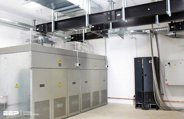 Why busbar trunking system is a space saving solution worth every penny (on photo: Busbars 3200A in Data Center, Italy; credit: graziadio.co.uk)
The rated voltage must not exceed 1,000 V for alternating voltage and 1,500 V for direct voltage!
Excluded from IEC 61439-6 (VDE 0660-600-6) are, among others, electrical busbar systems for luminaires (in accordance with IEC 60570 and VDE 0711-300). However, lighting systems can be connected to busbar trunking system and communication-capable tap-off units can be used to control consumers and to switch luminaires.
Planning is based on the incoming power (for example, rated and short circuit currents of the feeding transformers) and connection values of the busbar trunking system and additionally on the following data:
- Permissible voltage drop
- Required degree of protection
- Power system configuration
- Weighing of the supply concepts as cable system or busbar trunking system
- Short-circuit strength
- Overload and short-circuit protection
Configuration
Depending on the project conditions and various manufacturers, different busbar trunking systems can be selected:
- Sandwich design for compact dimensions.
- Ventilated busbar design for excellent heat dissipation.
(Attention: In the case of rising mains, the stack-effect of a closed box-type system may provide advantages) - Moulded busbar trunking system if highest demands are made on the degree of protection in critical environments.
The various systems may include different numbers of conductors. The PE conductor can be implemented as a separate busbar or as an enclosure. The N conductor can be a single conductor or it can be duplicated.
Conductors can be routed doubly in an enclosure to improve EMC!
Conductor material
Aluminium and copper are possible conductor materials. In the three years from 2010 to 2012, the copper price rose from about 4,000 to 6,000 euros per ton, the price for aluminium from about 1,300 to 1,600 € per ton1).
If aluminium is used, the necessary larger cross sections require more space.
While this is immaterial in HV power lines, it might be the knock-out criterion in a densely equipped switchgear cabinet or if routing busbar trunking systems in buildings. No criterion, however, is the oxidation capability of aluminium, as the aluminium buses from most of manufacturers are tin-plated so that there is no air-aluminium contact and the infamous disposition to flowing of aluminium cannot loosen the screw connections.
A rough clue for the use of the two materials is provided by the estimations of the material-specific relations as ratio:
- Market price for raw material Cu to Al is as 3 : 1
- Weight of Cu to Al is as 3 : 1
- Volumetric specific resistance (1 / electrical conductivity) is as 3 : 5
- Mass-related specific resistance (1 / electrical conductivity) is as 2 : 1
- Output-related costs per ampere (transmitted power) is as 5 : 1
Power transmission
Busbar trunking units without tap-off points are used for power transmission. They are available in standard lengths and custom lengths. Besides the standard lengths, the customer can also choose a specific length from various length ranges to suit individual constructive requirements.
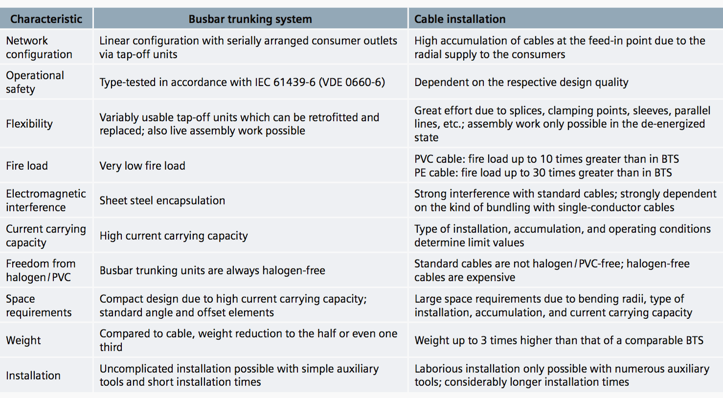
Both these costs and the time benefits during installation increase with the rated current rising. Table 1 summarizes the major differences between cable installations and busbar trunking systems.
Variable power distribution
In busbar trunking systems, electricity cannot just be tapped from a permanently fixed point as with a cable installation. Tapping points can be varied and changed as desired within the entire power distribution system. In order to tap electricity, you just have to connect a tap-off unit to the busbar system at the tapping point.
This way, a variable distribution system is created for linear and / or area-wide, decentralised power distribution.
Tap-off points are provided on just one or either side of the straight busbar trunking units. For each busbar trunking system, a wide range of tap-off units is available for the connection of consumers and electricity supply.
Fire protection
The following must be taken into account as to fire protection:
- Reduction of the fire load
- Prevention of fire spreading
The entire length has to be considered because the electrical routing may run through the whole building and is used to supply special installations and systems as for instance:
- Lifts with evacuation system
- Fire alarm systems
- Emergency power supply systems
- Ventilation systems for safety stairways, lift wells, and machine rooms of fire brigade lifts
- Systems to increase the pressure of the water supply for fire fighting
- Emergency lighting
“In order to prevent the development and spreading of fire and smoke, and to be able to effectively extinguish fires and save people and animals in the event of a fire” (state building regulations in Germany), neither fire nor flue gas may spread from one floor or fire section to another.
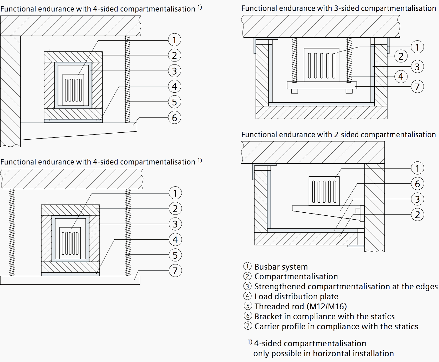
For busbar trunking systems, the fire walls between the various fire areas in the building complying with fire resistance classes S60, S90, and S120 in accordance with DIN 4102-9 can be ordered together with the busbar trunking system, depending on the design and type. The fire walls must have at least the same fire resistance class as the relevant wall or ceiling.
Because of the poorer ventilation and heat dissipation through the protective housing, the reduction factors specified by the manufacturers must be taken into account in later planning steps in order to determine the maximum permissible currents. A reduction factor of 0.5 can be assumed for an initial estimation.
Contrary to inexpensive cables and wires, the insulation used in busbar trunking system does not contain any materials that produce corrosive or poisonous gases in the event of a fire. There is also no burning of material in busbar trunking system so that the rooms remain clean and the escape routes are not impeded.
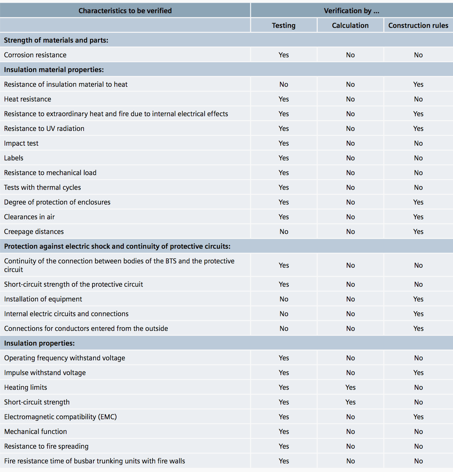
As for low voltage switchgear, a design verification can be accomplished for busbar trunking system. The design verification is accomplished dependent on the examined characteristic by way of testing, calculation, and construction verification (see Table 2 above).
Compared to the conventional cable installation, busbar trunking system provide many advantages with regard to network and installation technology, as depicted in Table 1 above.
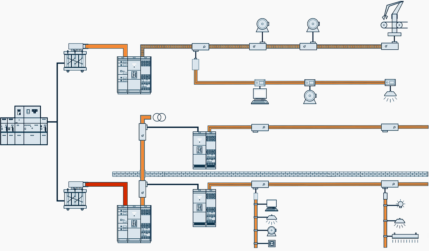
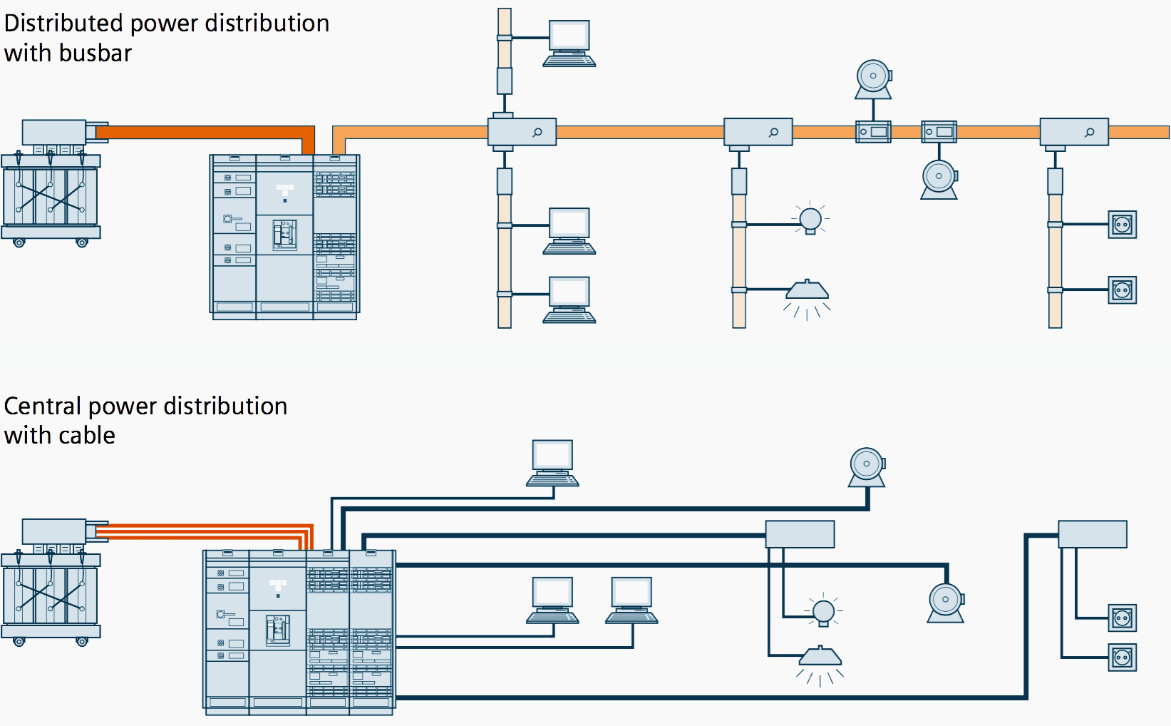
Wirings for simple electric power distribution systems
For demonstration purposes, Figure 3 shows wirings for simple electric power distribution systems. Modification and retrofitting of an electric power distribution system usually mean significantly higher expenditures of time and money for cable installations than for busbar trunking systems.
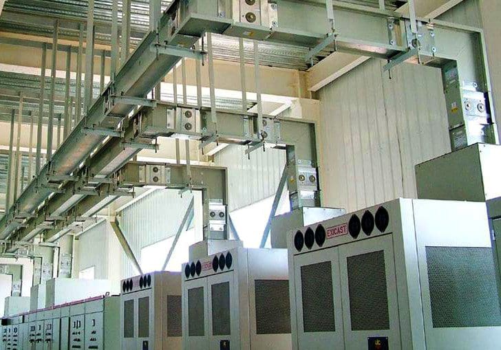
Space-saving solution, easy to install
The smaller the electrical equipment rooms and vertical riser shafts, and the greater the power density of electrical loads and power to be transmitted, the more important the issue of space becomes.
Busbar trunking systems also save space through their ability to change direction at right angles.
Reference // Planning of Electric Power Distribution – Technical Principles by Siemens


We are looking for a supplier of Busbar trunking to represent for Bangladesh market.
Hi Aminul,
I would like you to meet contact person if you still need any supplier. Please let me know. Thanks.
The article indicates important considerations in utilizing bus duct. As an operator of mission critical environments there are a few other really important points readers should be provided to ensure the bus duct remains a safe and reliable service. Those points being bus duct support systems and the splice plates.
When I suggest bus duct support is important, I’m not just referring to your threaded rods or unistrut being properly placed. The fastening point to the super structure plays a tremendous role in the reliability of the distribution arrangement. Keep in mind all roofs have some allowance for movement. If the bus duct is fastened to a super structure and combined roof structure that has varying degrees of movement the bus duct will be subject to stress that may be out of limits. Each manufacture outlines alignment measurement tolerances for their splices. be sure this is considered by the structural engineers. Remember the overhead structure may have relative movement not consistent with the equipment or building super structure.
The second and equally important factor for ensuring a successful bus duct install is maintenance requirements. The bus duct systems were never designed to be maintenance free. Each manufacturer has re-torqueing requirements for the splice points. Be sure to follow these closely while aslo adhering to the recommended service intervals.
Im totally agree with Mr. James Faccone. Mr. James has raised a very important point regarding “bus duct support”. When we start the installation activity of bust duct the methodology has to be defined according to the structural standards. It could much easier for the reader that what are standard procedure for busway installation in accordance to fulfill of Structural & mechanical compliance in general conditions.
I do agree with the comments made by Mr. James Faccone… Let us be always mindful that in some buildings there are expansion joints wherein we need also to provide flexible busducts to mitigate movement of a building. If budget permits, it would be also prudent and a good engineering practice to provide flexible busducts when joining not only when connecting with transformers but also with switchboards.
Moreover, there are no busducts which are maintenance free, however, some new busduct design includes bolts used in busduct joints which does not need regular re-tightening.