Reliability Of Capacitor Banks
Several problems contribute to the overall reliability or unreliability of capacitor banks. In a detailed analysis of Kansas City Power & Light’s automated capacitor banks, Goeckeler reported that blown fuses are KCP&L’s biggest problem, but several other problems exist.
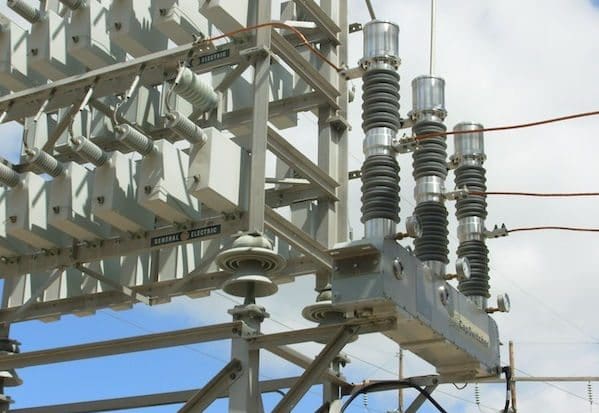
 Reliability Or Unreliability Of Capacitor Banks, Failure Modes and Case Ruptures (photo credit: nepsi.com)
Their automation with two-way communications allowed them to readily identify bank failures. The failure rates in Table 1 are high, much higher than most distribution equipment.
Capacitor banks are complicated, they have a lot of equipment to fail. Yet, failure rates should be significantly better than this.
Table 1 – Maintenance Needs Identified by Kansas City Power & Light’s Capacitor Automation System Based on Two Years of Dat
| Problem | Annual percent Failures |
| Primary fuse to capacitor blown (nuisance fuse operation) | 9.1 |
| Failed oil switches | 8.1 |
| Hardware accidentally set to “Local” or “Manual” | 4.2 |
| Defective capacitor unit | 3.5 |
| Miscellaneous | 2.4 |
| Control power transformer | 1.5 |
| TOTAL: | 28.8 |
The survey along with follow-up contacts highlighted several issues:
Misoperation of capacitor fuses
Many utilities have operations of fuses where the capacitor bank is unharmed. This can unbalance circuit voltages and reduce the number of capacitors available for
var support.
Review fusing practices to reduce this problem.
Controllers
Controllers were found “problematic” by a significant number of utilities. Some utilities had problems with switches and with the controllers themselves.
Lightning and faults
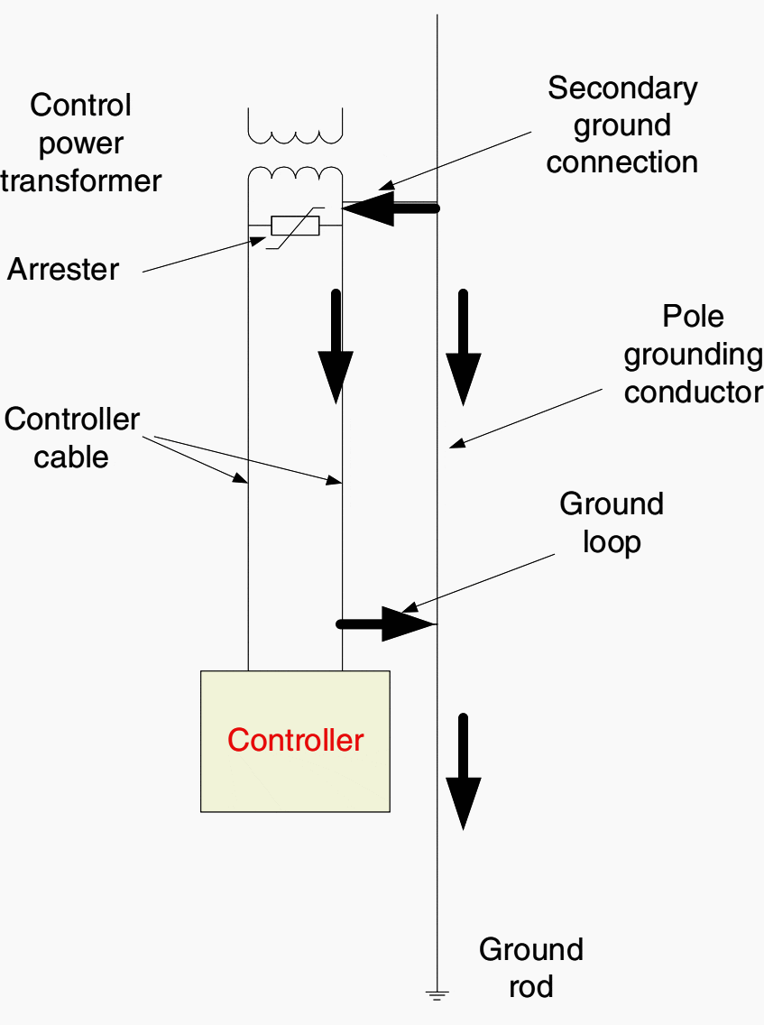
In high-lightning areas, controllers can fail from lightning. Controllers are quite exposed to lightning and power-supply overvoltages during faults. Review surge protection practices and powering and grounding of controllers.
Lightning surges can also reach the secondary conductors through distribution transformers. Surge transference is influenced by many factors including the voltage, turns ratio, electrostatic coupling and electromagnetic coupling of the windings, and the connected loads
Whenever possible, ground loops in the controller power wiring should be avoided. However, ground loops cannot always be eliminated, especially when the capacitor controller and control power transformer are not located on the same pole.
Human element
Many controllers are set up incorrectly unfotunately. Some controllers are hard to program, but this is no excuse for bad setting.
And, field crews often do not have the skills or proper attitudes toward capacitors and their controls. At some utilities, crews often manually switch off nearby capacitors (and often forget to turn them back on after finishing their work).
To reduce these problems, properly train crews and drive home the need to have capacitors available when needed.
How Capacitors Fail?
Capacitors can fail in two modes – Low current, progressive failure and high current, low-impedance failure.
1. Low current, progressive failure
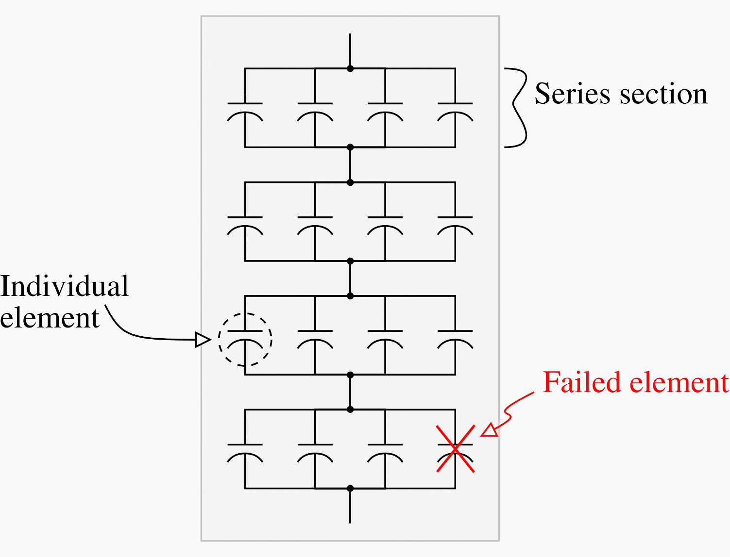
The dielectric fails in one of the elements within the capacitor (see Figure 1). With one element shorted, the remaining elements in the series string have increased voltage and higher current (because the total capacitive impedance is lower).
With more stress, another element may short out. Failures can cascade until the whole string shorts out. In this scenario, the current builds up slowly as elements successively fail.
2. High current
A low-impedance failure develops across the capacitor terminals or from a phase terminal to ground. A broken connector could cause such a fault.
Progressive Failure
Most failures are progressive. Sudden jumps to high current are rare. To detect progressive failures quickly, fusing must be very sensitive. Film-foil capacitors have few case ruptures — much less than older paper units.
An EPRI survey of utilities (EPRI 1001691, 2002) found that film-foil capacitor ruptures were rare to non-existent. This contrasts sharply with paper capacitors, where Newcomb (1980) reported that film/paper capacitors ruptured in 25% of failures.
Paper and paper-film capacitors have an insulating layer of paper between sheets of foil. When a breakdown in a pack occurs, the arc burns the paper and generates gas. In progressive failures, even though the current is only somewhat higher than normal load current, the sustained arcing can create enough gas to rupture the enclosure.
Before 1975, capacitors predominantly used polychlorinated biphenyls (PCB) as the insulating liquid. Environmental regulations on PCB greatly increased the costs of cleanup if these units ruptured (U.S. Environmental Protection Agency 40 CFR Part 761 Polychlorinated Biphenyls (PCBs) Manufacturing, Processing, Distribution in Commerce, and Use Prohibitions).
The environmental issues and safety concerns led utilities to tighten up capacitor fusing.
In modern film-foil capacitors, sheets of polypropylene film dielectric separate layers of aluminum foil. When the dielectric breaks down, the heat from the arc melts the film; the film draws back; and the aluminum sheets weld together.
Figure 2 shows capacitor-rupture curves from several sources. Most case-rupture curves are based on tests of prefailed capacitors. The capacitors are failed by applying excessive voltage until the whole capacitor is broken down.
The failed capacitor is then subjected to a high-current short-circuit source of known amperage for a given time. Several such samples are tested to develop a case-rupture curve.
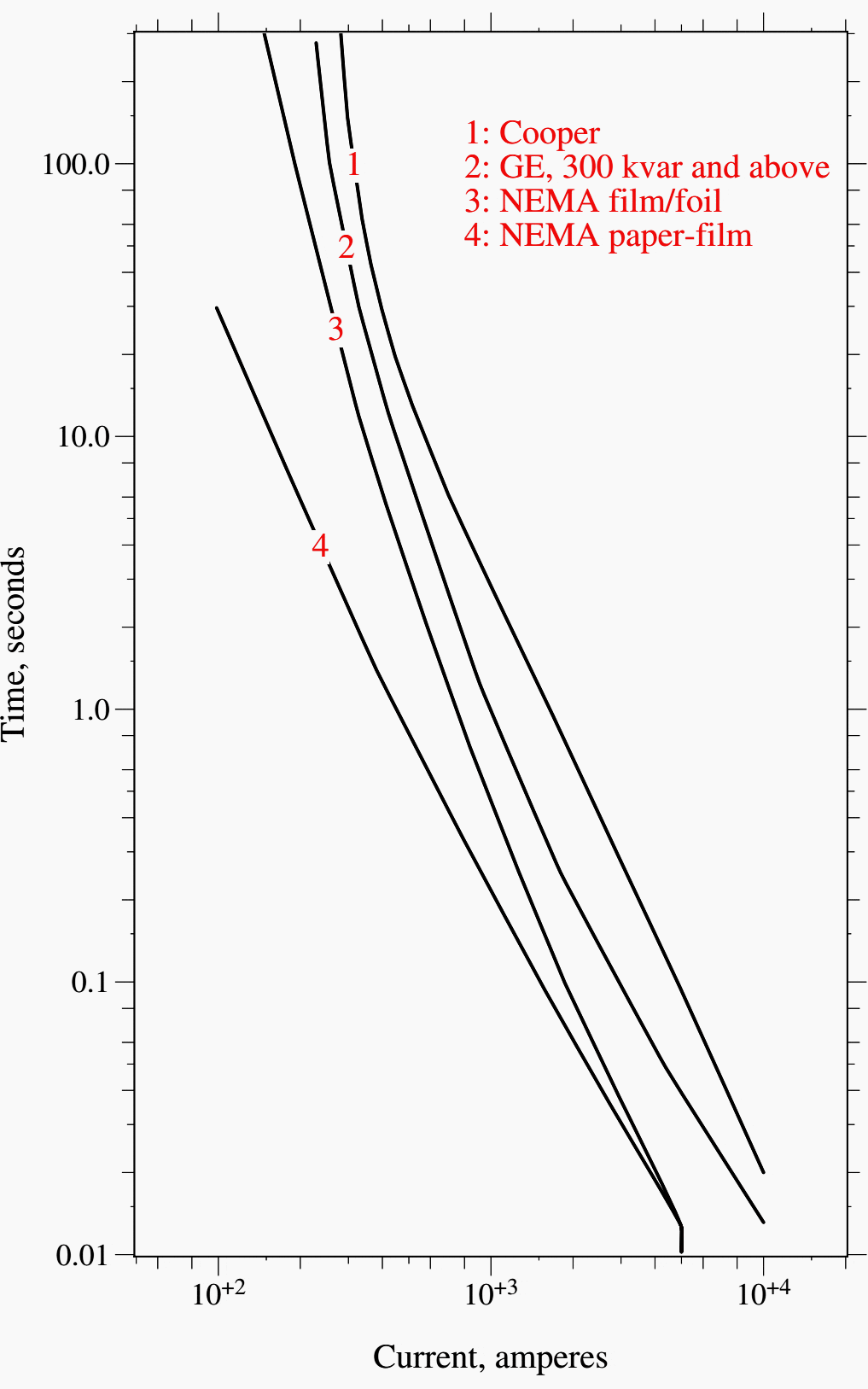
The case-rupture curves do not represent all failure modes. Such curves do not show the performance during the most common failures: low-current and progressive element failures (before all elements are punctured).
Although, thankfully, rare, high-current faults more severe than those tested for the rupture curves are possible. An arc through the insulating dielectric fluid can generate considerable pressure. Pratt et al. (1977) performed tests on film/foil capacitor units with arc lengths up to 3 in. (7.6 cm) in length. They chose 3 in. as the maximum realistic arc length in a capacitor as the gap spacing between internal series section terminals.
Capacitor switches, especially oil switches, are vulnerable to violent failure. This type of failure has not received nearly the attention that capacitor ruptures or distribution transformer failures have.
600 – 630 A, max. 170 kV
Potential transformers, current transformers, controller power-supply transformers, and arresters: these too can fail violently. Any failure in which an arc develops inside a small enclosure can rupture or explode.
In areas with high fault current, consider applying current-limiting fuses. These will help protect against violent failures of capacitor units, switches, and other accessories in areas with high fault current.
Table 1 – Number of Series Sections in Different Voltage Ratings
| Unit Voltage [V] | Manufacturer | ||
| A | B | C | |
| 2,400 | 2 | 2 | 2 |
| 7,200 | 4 | 4 | 4 |
| 7,620 | 5 | 5 | 4 |
| 13,280 | 8 | 8 | 7 |
| 13,800 | 8 | 8 | – |
| 14,400 | 8 | 8 | 8 |
When one element fails and shorts out, the other series sections have higher voltage, and they draw more current. Capacitor packs are designed with a polypropylene film layer less than one mil thick (0.001 in. or 0.025 mm), which is designed to hold a voltage of 2000 V.
Table 2 shows the number of series sections for several capacitors as reported by Thomas (1990).
More recent designs could have even fewer groups. One manufacturer uses three series sections for 7.2 to 7.96 kV units and six series sections for 12.47 to 14.4 kV units. As series sections fail, the remaining elements must hold increasing voltage, and the capacitor draws more current in the same proportion.
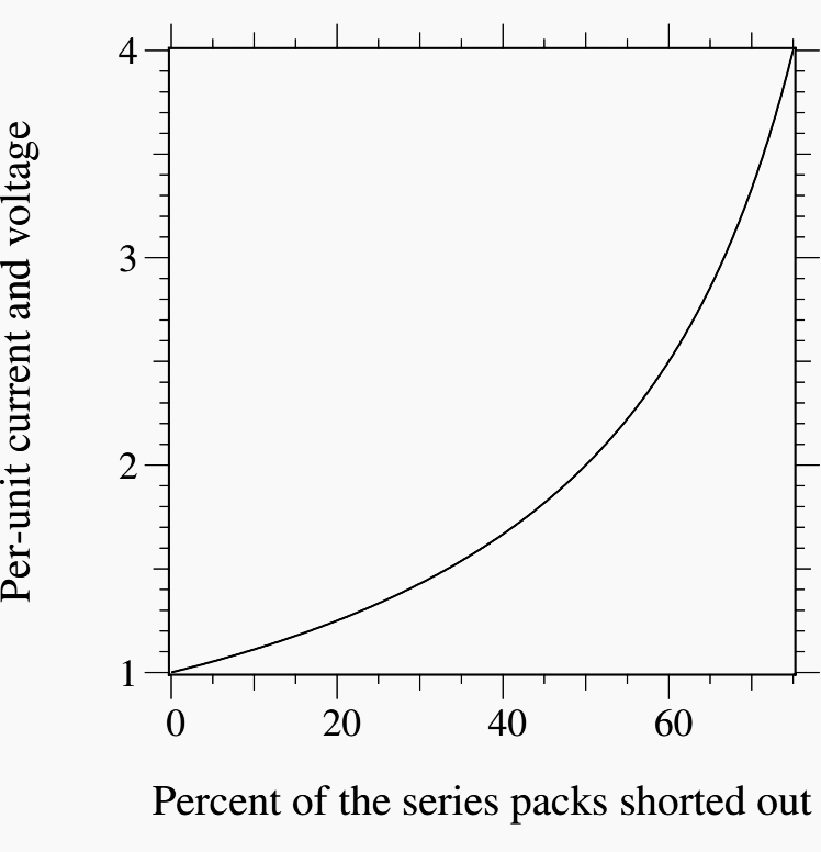
Figure 4 shows the effect on the per-unit current drawn by a failing unit and the per-unit voltage on the remaining series sections.
If a capacitor bank has multiple units on one phase and all units are protected by one fuse (group fusing), the total bank current should be considered. Consider a bank with two capacitor units. If one unit loses half of its series sections, that unit will draw twice its nominal current.
The group — the two units together — will draw 1.5 times the nominal bank load. (This is the current that the fuse sees.)
Capacitor bank used at grid sub station 33 kV
References //
- Electric power distribution equipment and systems by T.A. Short (Purchase hardcopy from Amazon)
- Lightning Protection of Distribution Capacitor Controllers by F. D. Crudele, Member, IEEE, P. E. Sutherland, Senior Member, IEEE
and T. A. Short, Senior Member, IEEE