
Introduction
The direct starting (Direct On Line, DOL) is the simplest and most cost-efficient method of starting a motor. This is assuming that the power supply can easily deliver the high starting current and that the power transmission components and the working machine are suitable for the high starting torques.
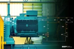
With direct starting, the poles of contactor and motor protective device are connected to the pole conductors (Figure 1) and the operating current of the motor flows through them.

The motor protective device must therefore be adjusted to the rated operational current of the motor.
- AC-3 Squirrel-cage induction motors: Starting, switching off during running
- AC-4 Squirrel-cage induction motors: Starting, plugging, inching
For AC-3 operation, allowance must always be made in practice for sporadic inching operations, for example during commissioning, in case of faults or in service work.
Contactors from Rockwell Automation comply with these requirements and may be rated without risk according to AC-3 values; for the large majority of devices, the rated operational currents for the utilization categories AC-3 and AC-4 are the same. A considerable proportion of AC-4 operations or exclusive AC-4 operation is in practice relatively rare. In such cases, a high frequency of operation is often required at the same time and a high electrical life span is expected.
Thus the contactor must be selected according to these two criteria. In most cases a larger contactor must be used than would correspond to the maximum permissible AC-4 rated operational current.
Starting time
The starting time is an important parameter in starter engineering, as the starting current can be many times higher than the rated currents of motor and switchgear and correspondingly places the latter under thermal loading.
It depends on the torque of the motor and hence on the selected starting method, as well as on the torque characteristic of the load.
The duration of so called no-load starting, i.e. starts without loading of the drive, typically lies, depending on motor size, in the time range of under 0.1 to around 1 s, starting under load (but without large flywheel masses) up to around 5 s. For centrifuges, ball mills, calenders, transport conveyors and large fans, the start times can extend to minutes.
In the case of pumps and fans it should be noted that the pumped material (liquid, air) contributes to the effective inertial mass.
The above given approximate values apply for direct starting. The times are correspondingly extended with starter methods with reduced starting current and torque.
With respect to the permissible starting time of the respective motor, the manufacturer’s documentation is definitive.
Reversing starters
In a reversing starter the motor is switched via two contactors, one for each direction. If the motor is started from rest, the contactor is selected according to utilization category AC-3.
Often however the motor direction is changed while it is running (plugging), which means a correspondingly higher loading of the contactors and hence requires selection according to utilization category AC-4.

Direct reversing requires a reversing delay between the contactors – for example by means of a short-term delay – of around 40 ms, to prevent short-circuits between phases. In addition to electrical interlocking of contactors of reversing starters, mechanical interlocking is recommended.
Corresponding precautions as for reversing starters are required for plugging with stopping at standstill. In this case when the motor comes to rest, the braking contactor (for example controlled by a speed sensor) is switched off and the motor is hence disconnected from the supply.
Squirrel Cage Motors (VIDEO)
Cant see this video? Click here to watch it on Youtube.
Resource: Allen Bradley – Low Voltage Switchgear and Controlgear


Thank you for your contribution to improve my knowledge
Why we are using DOL startor for large motor as 500KW and above ,why not Star delta ,or auto transformer.