
Individual PFC for transformers
The utility regulations for the allowable size of capacitors permanently connected to a transformer vary according to region. Before installing a PFC system of this type, it is therefore advisable to consult the utility company concerned.

The modern design of transformer features core laminations that only require a small amount of power for reversal of magnetization. If the capacitor power rating is too high, overvoltage conditions may occur during no-load operation.
If capacitors with fuse switch disconnectors are connected directly to the transformer terminals, the designer should be aware of the fact that the lines to the capacitor are dimensioned for the full short-circuit power.
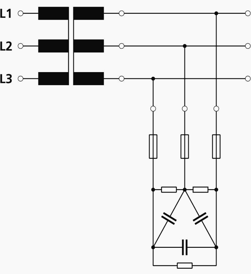
The capacitor with fuse switch can be directly connected to the terminals of the transformer. This means that the lines to the capacitor must be dimensioned for the full short-circuit power. The fuse switches are operated under purely capacitive load.
They must therefore never be withdrawn when under load or dangerous arcing may otherwise occur!
Table 1 – Approximate capacitor ratings for individual power factor correction of transformers according to the German Association of Energy and Water Industries (BDEW)
| Transformer nominal rating [kVA] | Capacitor power rating [kvar] |
| 100 – 160 | 2.5 |
| 200 – 250 | 5.0 |
| 315 – 400 | 7.5 |
| 500 – 630 | 12.5 |
| 800 | 15.0 |
| 1000 | 20.0 |
| 1250 | 25.0 |
| 1600 | 35.0 |
| 2000 | 40.0 |
If it is possible to disconnect the capacitor even when the transformer is switched on, a power capacitor with an automatic circuit breaker must be used.
Individual PFC for motors
The capacitor power rating should be some 90% of the motor apparent power when running under no-load conditions.
Required capacitor power rating:
Qc [VAR] = 0.9 × √3 × V × I0
where: I0 is no-load motor current.
This produces a power factor of about 0.9 under full load and 0.95 – 0.98 under no-load conditions. The German Association of Energy and Water Industries (BDEW) recommends the approximate capacitor ratings for induction motors running at 1500 min-1.
The values given in the table should be increased by 5% for motors running at 1000 min-1, or by 15% for motors running at 750 min-1.
| Title: | Power Factor Correction: Theory, Methods, Applications, Specification and Installation – Peter Riese, FRAKO |
| Format: | |
| Size: | 4.6 MB |
| Pages: | 72 |
| Download: | Right here | Video Courses | Membership | Download Updates |


Your website (and its content) makes me regretting I did not follow a career in electrical/electronics engineering.
Very useful infomation.