
400/220/132 KV substation
The first step towards the design of a 400/220/132 KV substation is to determine the load that the substation has to cater and develop it accordingly. The substation is responsible for catering bulk power to various load centres distributed all around through 220 KV and 132 KV substations.

The substation is fed 1316 MW power from 3 generating stations A,B,C through 400 KV single circuit lines working at around 87% loading.
The power is received on 400 KV busbar (double main and transfer bus scheme). 636 MW power is dispatched to a 400 KV substation ‘a’ catering an area having diversity factor 1.1 through 400 KV double circuit lines working at 70% loading. The remaining 680 MW is fed to three 315 MVA (=3 x 10⁵ MVA units) autotransformers working at an average 80% loading and 0.9 power factor.
The rest i.e.640 MW is fed to the 220 KV busbar (double main and transfer bus scheme). To increase the reliability of the system the 220 KV busbar is also fed from 2 other substations.
A single circuit line from station E working at 68% loading supplies 85 MW while a double circuit line from station D working at 70% loading supplies 175 MW power to the busbar. This ensures continuity of supply to certain extent even when an entire 315 MVA transformer unit fails to operate.
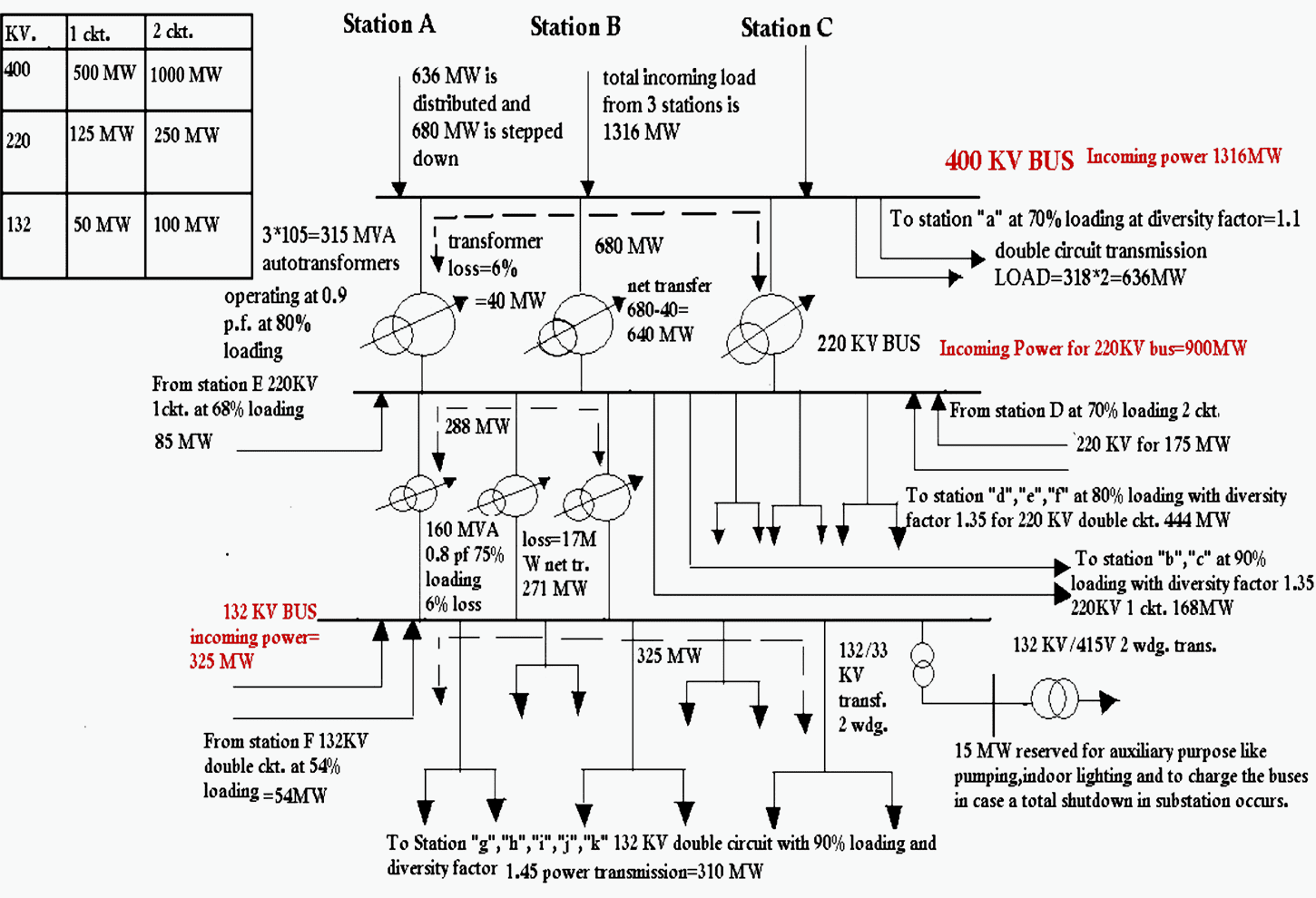
Thus total incoming power on 220 KV bus is (640+175+85 =)900 MW. From the 220 KV bus two 220 KV single circuit lines are drawn at 90% loading to supply power to 220KV substations ‘b’and ‘c’ working at a diversity factor of 1.35 to cater 112.5 MW each.
Three 220 KV double circuit lines working at 80% loading feeds substations ‘d’,’e’,’f’ working at a diversity factor of 1.35 to meet a demand of 200 MW each. The remaining 288 MW is fed to three 160 MVA autotransformers working at an average 75% loading and 0.8 power factor.
The 160 MVA transformers step down the voltage from 220 KV to 132 KV. 6% of the input power 288 MW i.e. around 17 MW power is lost in the transformers. The rest i.e.271 MW is fed to the 132 KV busbar(double main bus scheme).
A 132 KV double circuit line working at 54% loading delivers 54 MW power to the 132 KV bus. This arrangement similar to the one for 220 KV bus and ensures that the substation is not inconvenienced to a great extent if somehow a 160 MVA transformer goes out. Total incoming power on 132 KV bus is 271+54=325 MW.
From the 132 KV bus five 220 KV double circuit lines working at 90% loading feeds substations ‘g’,’h’,’i’,’j’,’k’ working at a diversity factor of 1.45 to meet a demand of 90 MW each. After dispatching 310 MW power, the remaining 15 MW power available from 132 KV bus is stepped down using 132/33 KV & 33/0.415 KV two winding transformers.
This power is used for auxiliary purposes like pumping, lighting, AC and ventilation purposes within the substation to ensure its smooth functioning.
| Title: | Design Of 400/220/132 KV 1316 MW Power Substation |
| Format: | |
| Size: | 3.30 MB |
| Pages: | 117 |
| Download: | Here 🔗 (Get Premium Membership) | Video Courses | Download Updates |

The single diagram indicates loss of 6 % power by transformers.Is it not high as transformer efficiency is normally morethan 98%.This needs to be verified