
Programmable logic controller (PLC)
A Programmable Logic Controller (PLC), also referred to as programmable controller, is the name given to a type of computer commonly used in commercial and industrial control applications.
PLCs differ from office computers in the types of tasks that they perform and the hardware and software they require to perform these tasks.
While the specific applications vary widely, all PLCs monitor inputs and other variable values, make decisions based on a stored program, and control outputs to automate a process or machine. This course is meant to supply you with basic information on the functions and configurations of PLCs with emphasis on the S7-200 PLC family.
Basic PLC operation
The basic elements of a PLC include input modules or points, a Central Processing Unit (CPU), output modules or points, and a programming device. The type of input modules or points used by a PLC depend upon the types of input devices used. Some input modules or points respond to digital inputs, also called discrete inputs, which are either on or off. Other modules or inputs respond to analog signals.
These analog signals represent machine or process conditions as a range of voltage or current values.
The primary function of a PLC’s input circuitry is to convert the signals provided by these various switches and sensors into logic signals that can be used by the CPU. The CPU evaluates the status of inputs, outputs, and other variables as it executes a stored program. The CPU then sends signals to update the status of outputs.
The programming device is used to enter or change the PLC’s program or to monitor or change stored values. Once entered, the program and associated variables are stored in the CPU. In addition to these basic elements, a PLC system may also incorporate an operator interface device of some sort to simplify monitoring of the machine or process.
In the simple example shown below, pushbuttons (sensors) connected to PLC inputs, are used to start and stop a motor connected to a PLC output through a motor starter (actuator). No programming device or operator interface are shown in this simple example.
Hard-Wired Control
Prior to PLCs, many control tasks were performed by contactors, control relays and other electromechanical devices. This is often referred to as hard-wired control.
Circuit diagrams had to be designed, electrical components specified and installed, and wiring lists created. Electricians would then wire the components necessary to perform a specific task. If an error was made, the wires had to be reconnected correctly. A change in function or system expansion required extensive component changes and rewiring.
Advantages of PLCs
PLCs not only are capable of performing the same tasks as hard-wired control, but are also capable of many more complex applications. In addition, the PLC program and electronic communication lines replace much of the interconnecting wires required by hard-wired control.
Some of the additional advantages of PLCs are as follows:
- Smaller physical size than hard-wire solutions.
- Easier and faster to make changes.
- PLCs have integrated diagnostics and override functions.
- Diagnostics are centrally available.
- Applications can be immediately documented.
- Applications can be duplicated faster and less expensively.
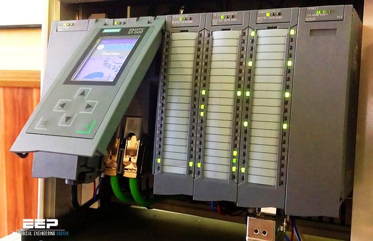
Siemens PLCs
Siemens makes several PLC product lines in the SIMATIC® S7 family. They are: S7-200, S7-300, and S7-400.
| Title: | Basics of PLCs – SIEMENS |
| Format: | |
| Size: | 4.0 MB |
| Pages: | 84 |
| Download: | Right here | Video Courses | Membership | Download Updates |

Appreciated.
PLC programs classes needed
Me gusta la automatización y siempre estoy interesado en la información de.PLC, este articulo es muy interesante
good
Sir/mam
I am the biggner in plc and also for automation in my company there we use ABB plc please help me for my future I study your blog please share me the easy steps for start the tour
i am beginner of PLC. i need support to learn plc system and i m very much interested to learn. i m crazy about it. any how i want to be a specialist on plc . plz give me supprt. it was really helpful to me.
hace muchos años empece a estudiar electricidad, para mì los plcs eran una novedad,con el paso del tiempo he notado, su importancia en la actul tecnologìa, por eso me encantaria, retomar dicha informacion. Muchas gracias.
this always meet my demand
On the simplified comparison between PLCs and Computers, I would like to add …
* PLCs use a micro-processor that can only impliment 1 task at a time in sequence, computers use a full blow processor, most 2 full processors or more and do multi-tasking.
* A crash on computer means at most, restoring operating system, a crash on PLC can result in damage to man or machine.
Note: PACs are much different than PLCs, and actually quite close to being a computer as PACs have 2 processors and do multi-tasking like a computer does.