
Power factor test
The power factor test is a maintenance test used to determine the insulation system dielectric power loss by measuring the power angle between an applied AC voltage and the resultant current. Power factor is defined as the ratio of the power dissipated divided by the input volt-ampere multiplied by 100%.
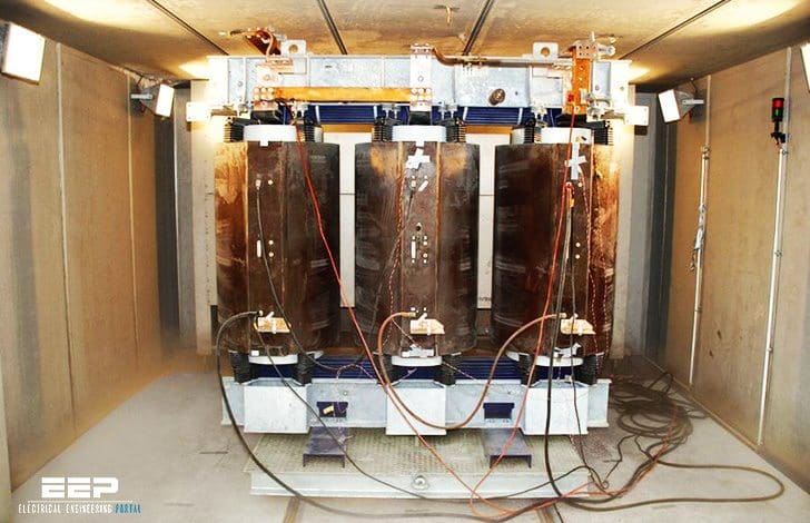 Performing power factor test on dry-type transformer during commissioning (photo credit: sgb-smit.com)
This test may be required to be performed during the acceptance testing stage to establish a baseline reading for future test comparison.
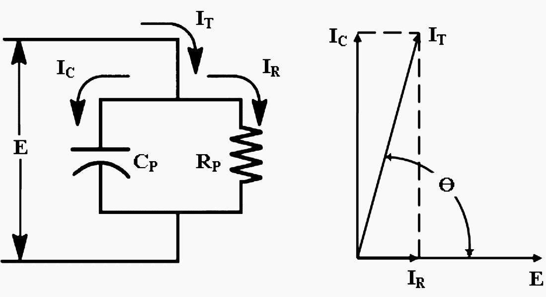
Dielectric losses in and power factor can be calculated by:
Watts = E × IT × Cosine Ө
Power factor = Cosine Ө = Watts / (E × IT)
Power factor test is performed for detecting insulation deterioration or degradation usually caused by moisture, carbonization or other forms of contaminants of the winding and bushing. Winding distortions results in a change in winding capacitance and short-circuited and partially short-circuited turns result in abnormally high excitation current.
Types of transformers that are normally subjected to the power factor test are:
- Two winding transformers
- Three winding transformer
- Auto-transformers
- Instrument transformers
General conditions required for testing transformers are:
- The unit must be de-energized and isolated from the power system including the neutral connection from ground.
- Transformer enclosure must be properly grounded and applicable to when testing spare units.
- All terminal of each winding are short-circuited together including the neutral terminals. This will minimize the effect of winding inductance
during testing. - Load tap changer (LTC) should be set of neutral if it has arrester-type elements that are not effectively short circuited in the neutral position.
The power factor test typically applies a test voltage less than the stress working levels of the equipment. Refer to Table 1.
Table 1 – Recommended power factor test voltage for dry-type power transformer connected in delta and ungrounded-wye
| Winding rating Line-to-line, kV | Test Voltage Line-to-ground, kV |
| Above 14.4 | 2 and 10 |
| 12 to 14.4 | 2, 10 and at operating line-to-ground voltage |
| 5.04 to 8.72 | 2 and 5 |
| 2.4 to 4.8 | 2 |
| Below 2.4 | 1 |
Note // Transformer windings provided with neutral insulation rating which is less than the line insulation rating should be tested below the neutral insulation rating level.
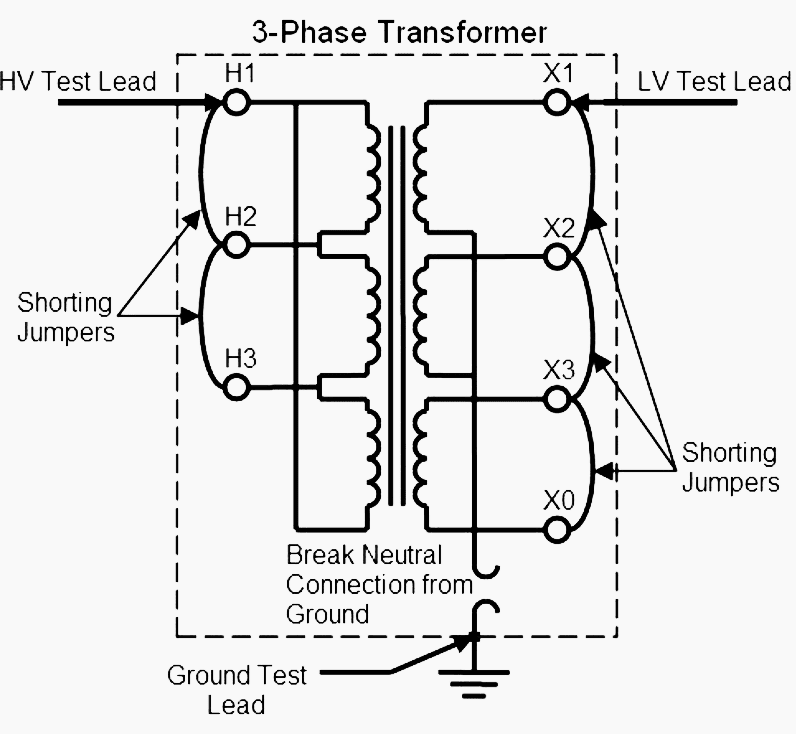
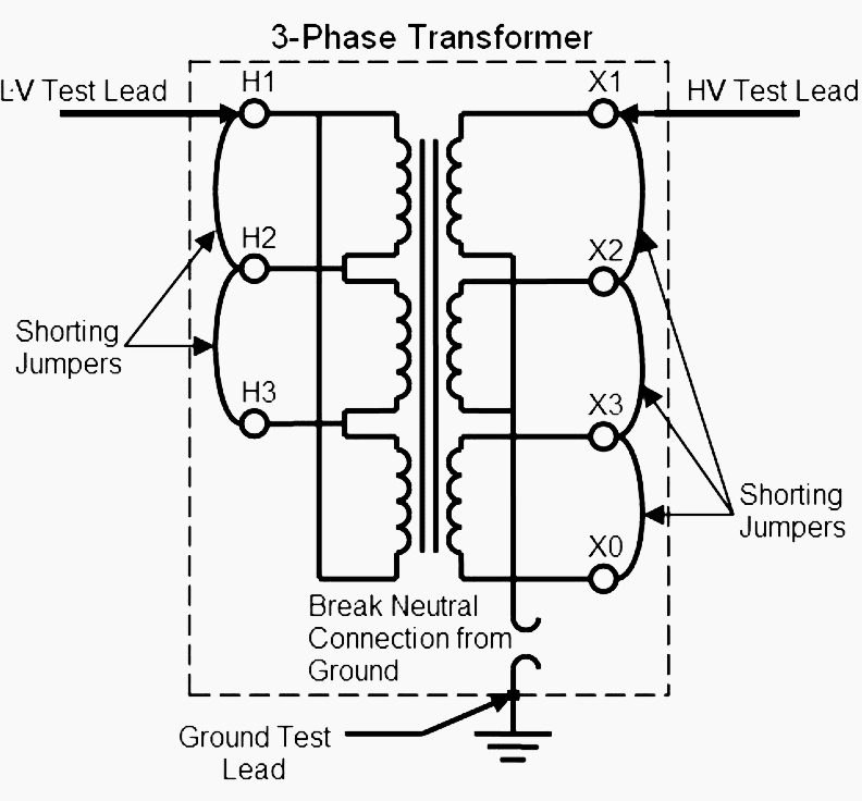
The required tests are noted in Table 2 and its connection is shown in Figure 2 and Figure 3. The difference between the high voltage winding tests and the low voltage winding tests are the placement of the test leads and the test voltage levels. Test 3 and test 8 of Table 2 should generate the same value as they both measure the same capacitance between the windings.
Table 2 – Power Factor test connection for two winding dry-type transformer
| Test number | Test mode | Energized winding | Ground | Guard | UST | Measure |
| 1 | GST | High | Low | – | – | CH+CHL |
| 2 | GST | High | – | Low | – | CH |
| 3 | UST | High | – | – | Low | CHL |
| 4 | Calculate Test 1 minus Test 2 | CHL | ||||
| 5 | GST | Low | High | – | – | CL+CHL |
| 6 | GST | Low | – | High | – | CL |
| 7 | UST | Low | – | – | High | CHL |
| 8 | Calculate Test 5 minus Test 6 | CHL | ||||
HV winding power factor test
- Isolate transformer
- Isolate Neutral Connection
- Install shorting jumpers on H1, H2 and H3
- Install shorting jumpers on X1, X2, X3 and X0
- Apply Specified test voltage at ramp rate in 15 seconds
- Test at specified voltage for 1 minute
- Reduce test voltage to zero at ramp rate in 5 seconds
LV winding power factor test
- Isolate transformer
- Isolate Neutral Connection
- Install shorting jumpers on H1, H2 and H3
- Install shorting jumpers on X1, X2, X3 and X0
- Perform a GST test
- Perform a Guard test
- Perform an UST test
- Confirm capacitance value from GST test minus Guard test equal UST test
Always ground to the previously energized terminal with a grounding stick before making any connection changes to bleed off any electrical charge that may be present. Leave the grounding connected until connection changes is completed and before the start of the next test.
Power factor test procedure (Two winding dry-type transformer)
- Isolate the equipment, apply working grounds to all incoming and outgoing cables and disconnect all incoming and outgoing cables from the transformer bushing terminals. Disconnected cables should have sufficient clearance from the switchgear terminals greater that the phase spacing distance.Use nylon rope to hold cable away from incoming and outgoing terminals as required.
- Isolate the neutral bushing connection if applicable from the transformer grounding bar.
- Short-circuit all high voltage bushing terminals together.
- Short-circuit all low voltage bushing terminals and the neutral bushing terminal together.
- Connect the power factor test set. Refer to Table 2 for the test measuring mode and associated test number.
- Apply the specified test voltage levels as noted in Table 2.
- Record power factor and watts loss values.
- Repeat step 5 to 7 until all tests are completed
Table 2 -Standard kVA Ratings for Dry-Type Transformers
| Single phase | Three phase | Single phase | Three phase |
| 2 | 6 | 333 | 1000 |
| 3 | 9 | 500 | 1500 |
| 5 | 15 | 667 | 2000 |
| 10 | 30 | 833 | 2500 |
| 15 | 45 | 1000 | 3000 |
| 25 | 75 | 1250 | 3750 |
| 37 | 112 | 1667 | 5000 |
| 50 | 150 | 2500 | 7500 |
| 75 | 225 | 3333 | open-ended |
| 100 | 300 | 5000 | |
| — | 450 | open-ended | |
| 167 | 500 | – | |
| 250 | 750 | – |
Measuring capacitance and power factor or dissipation factor
The condition of the bushings and the overall insulation of power transformers can be investigated by measuring the capacitance and dissipation factor, also known as the tangent delta, or power factor.
Aging and decomposition of the insulation, or the ingress of water, increases the losses and thus more energy is turned into heat in the insulation. The level of this dissipation is expressed by the dissipation factor or power factor.
Power factor testing
In this video you will learn about means to measure the quality of the insulation of power transformers and bushings, such as power factor or dissipation factor measurement, and measuring capacitance.
Possible causes for a reduction in insulation quality are also explained.
TanDelta/Power Factor Testing
Reference // Substation commissioning course – Dry-type transformers by Raymond Lee, Technical Trainer


Can you share what are typical acceptable power factor results for oil type instrument transformers and dry type instrument transformers rated for 69kv and 138kv voltages. The IEEE guidelines are not clear in terms of what the acceptable result should be especially for dry type resin encapsulated type units.
excellent article alongwith videos . Need some detail about how to improve energy efficiency at HV and LV levels ( Grid Station , distribution system and at home)
oil test transformar –(25kva—–5000kva) –evry think abaut it
The tip-up test does not mention it in dry transformers, why?