
Estimated Study Time: 7 minutes
Exciting current inrush
When a transformer is initially energized, there is a phenomenon known as exciting current inrush. Although inrush currents are not generally as damaging as fault currents, the duration of exciting current inrush is on the order of seconds (as compared to on the order of cycles with fault currents).
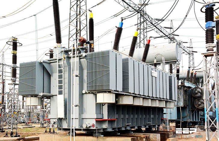 When does exciting current inrush occur in power transformer? (on photo: Two 220kV power transformers at Bahawalpur and Burhan; credit: ntdc.com.pk)
Exciting current inrush conditions also occur much more frequently than short circuits, so this phenomenon is worth exploring.
Consider what happens when initially energizing a single phase transformer. Flux in the core is equal to the integral of the excitation voltage.
If the circuit is closed when the voltage is passing through zero and the initial flux is zero, the sinusoidal flux will be fully offset from zero. The full-offset flux has a peak value that is twice the peak value of a symmetrical sinusoidal flux.
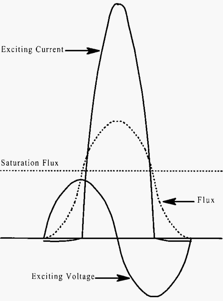
In other words, the peak flux for a fully offset wave can approach two times the normal peak flux, and this is generally sufficient to drive the core into saturation.
At this point, the only thing that limits exciting current is the air-core impedance of the winding, which is several orders of magnitude smaller than the normal magnetizing impedance.
Therefore, the exciting current is much greater than the normal exciting current during the half cycle when the core is saturated. During the opposite half cycle, the core is no longer saturated and the exciting current is approximately equal to the normal exciting current.
This is illustrated in Figure 1.
The situation is even more extreme when there is residual flux in the core and the direction of the residual flux is in the same direction as the offset in the sinusoidal flux wave. This is illustrated in Figure 2 below.

Let’s find the peak inrush current
To find the peak inrush current, limited only by the air-core reactance, it is convenient to calculate the inductance of the winding using cgs units:

where:
- N – number of turns in the coil
- Amt – area inside the mean diameter of the coil, cm2
- l – axial length of the coil, cm
- L – inductance of the coil, μH
The flux generated by the inductance φL is equal to the residual flux plus 2 times the normal flux change minus the saturation flux, since the saturation flux is in the iron. But φL is related to the inductance and the current:

Therefore, the peak inrush current is expressed in the cgs system of units as follows:

where:
- Ipeak is in amps and
- φr – residual flux
- φn – normal flux change
- φs – saturation flux
Without resistance in the circuit, each successive peak would have the same value and the current inrush would go on indefinitely. With resistance in the circuit, however, there is a significant voltage drop across the resistance and the flux does not have to rise quite as high as the previous cycle.
The integral of the voltage drop represents a net decrease in the flux required to support the applied voltage. Since the i × R voltage drop is always in the same direction, each cycle decreases the amount of flux required. When the peak value of flux falls below the saturation value of the core, the inrush current disappears. The rate of decay is not exponential although it resembles an exponentially decaying current.
IMPORTANT! For large power transformers, the inrush current can persist for several seconds before it finally dies off.
The line reactance has the effect of reducing the peak inrush current by simply adding inductance to the air-core inductance of the winding. There is a definite relationship between inrush current and short circuit current because both are related to the air-core inductance of the windings.
Remember that short circuits tend to exclude flux from the core.
The whole problem of analyzing exciting current inrush gets much more difficult when 3-phase transformers are involved. This is because the phase angles of the exciting voltages are 120° apart, there are interactions of currents and voltages between phases, and the three poles of the switching device do not close at exactly the same time.
Nevertheless, it is safe to say that the peak magnitude of inrush current for three-phase transformers approaches the short circuit current levels.
One of the interesting features of exciting current inrush is that since the current is fully offset, there are large percentages of even harmonics present. Even harmonics are otherwise rarely encountered in power circuits.
Sympathetic inrush
There is also a phenomenon known as sympathetic inrush, where a transformer that is previously energized will exhibit a sudden change in current when a nearby transformer is switched on. Sympathetic inrush is caused by changes in line voltages from the inrush currents of the second transformer.
Related electrical guides & articles


Edvard Csanyi
Hi, I'm an electrical engineer, programmer and founder of EEP - Electrical Engineering Portal. I worked twelve years at Schneider Electric in the position of technical support for low- and medium-voltage projects and the design of busbar trunking systems.I'm highly specialized in the design of LV/MV switchgear and low-voltage, high-power busbar trunking (<6300A) in substations, commercial buildings and industry facilities. I'm also a professional in AutoCAD programming.
Profile: Edvard Csanyi

Hi Edvard,
I’m a bit puzzled by your definition of air-core impedance and magnetising impedance. Does the transformer have two difference impedance values depending whether the transformer is magnetising (inrush) or in normal on-load operation?
Thank you for the information, the subject is exciting, but what is the change in the inrush current if the transformer is on load?
Regards