
Purpose of grounding transformer
Grounding transformers are sometimes used on distribution systems. A grounding transformer provides a source for zero sequence current. Sometimes they are used to convert a 3-wire, ungrounded circuit into a 4-wire, grounded circuit.
 Why do we use grounding transformers - zig-zag and grounded wye-delta connections (photo credit: swedishneutral.se)
Figure 1 (see below) shows the two most common grounding transformers. The zig-zag connection is the most widely used grounding transformer.
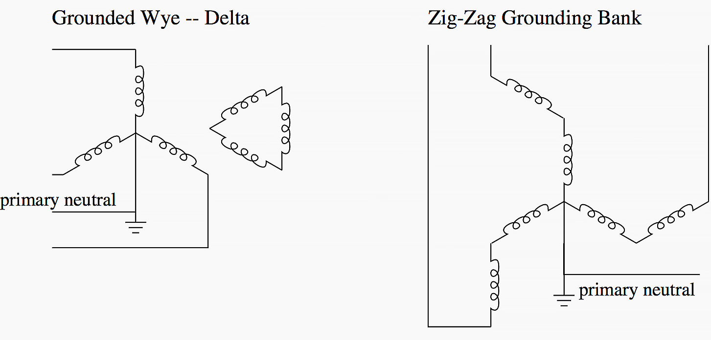
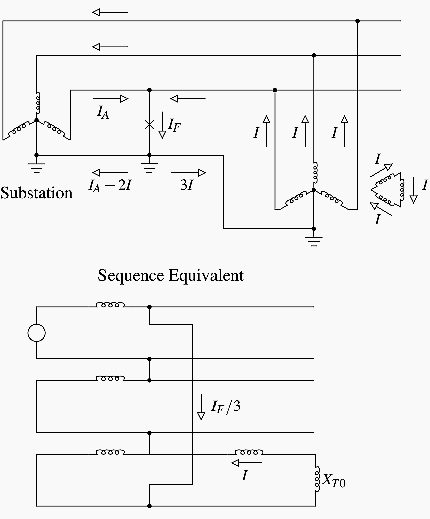
Figure 2 shows how a grounding bank supplies current to a ground fault. Grounding transformers used as the only ground source to a distribution circuit should be in service whenever the three-phase power source is in service.
If the grounding transformer is lost, a line-to-ground causes high phase-to-neutral voltages on the unfaulted phases, and load unbalances can also cause neutral shifts and overvoltages.
A grounding transformer must handle the unbalanced load on the circuit as well as the duty during line-to-ground faults.
If the circuit has minimal unbalance, then we can drastically reduce the rating of the transformer. It only has to be rated to carry short-duration (but high-magnitude) faults, normally a 10 seconds or 1 minute rating is used. We can also select the impedance of the grounding transformer to limit ground-fault currents.
Each leg of a grounding transformer carries one-third of the neutral current and has line-to-neutral voltage. So in a grounded wye – delta transformer, the total power rating including all three phases is the neutral current times the line-to-ground voltage:
S = VLG × IN
A zig-zag transformer is more efficient than a grounded wye–delta transformer. In a zig-zag, each winding has less than the line-to-ground voltage, by a factor of √3, so the bank may be rated lower:
S = VLG × IN / √3
ANSI/IEEE Std. 32-1972 requires a continuous rating of 3% for a 10-sec rated unit (which means the short-time rating is 33 times the continuous rating).
For both the zig-zag and the grounded wye-delta, the zero-sequence impedance equals the impedance between one transformer primary and its secondary.
Another application of grounding transformers is in cases of telephone interference due to current flow in the neutral/ground. By placing a grounding bank closer to the source of the neutral current, the grounding bank shifts some of the current from the neutral to the phase conductors to lower the neutral current that interferes with the telecommunication wires.
Grounding transformers are also used where utilities need a ground source during abnormal conditions.
One such application is for a combination feeder that feeds secondary network loads and other non-network line-to ground connected loads. If the network transformers are delta-grounded wye connected, the network will backfeed the circuit during a line-to-ground fault.
If that happens while the main feeder breaker is open, the single-phase load on the unfaulted phases will see an overvoltage because the circuit is being back fed through the network loads as an ungrounded system. A grounding bank installed on the feeder prevents the overvoltage during backfeed conditions. Another similar application is found when applying distributed generators.
A grounded wye-delta transformer is often specified as the interconnection transformer to prevent overvoltages if the generator drives an island that is separated from the utility source.
Even if a grounding bank is not the only ground source, it must be sized to carry the voltage unbalance. The zero-sequence current drawn by a bank is the zero-sequence voltage divided by the zero-sequence impedance:
I0 = V0 / Z0
Severe voltage unbalance can result when one phase voltage is opened upstream (usually from a blown fuse or a tripped single-phase recloser). In this case, the zero-sequence voltage equals the line-to-neutral voltage. The grounding bank will try to hold up the voltage on the opened phase and supply all of the load on that phase, which could severely overload the transformer.
Reference // Electric Power Distribution Equipment and Systems By T.A. Short (Get hardcopy from Amazon)


How to calculate the per-phase impedance in ohms for the zig-zag grounding transformer for the following example?
The transformer is an 85MVA base rating, 138/34.5kV, star/delta, Delta secondary, the zig-Zag will be on 34.5kV delta sec to feed the station load, and the required Neutral current is 500A for 10Sec.
Z= 19.9/( 500/3) or 19.9/( 500/√3)????
Please clarify
In your sample problem of 24.9 MVA with a 1 min rated bank, I believe you sized the 0.75 MVA continuous rating in accordance with a 10 second rated bank instead of the 1 minute:
24.9 MVA x 0.07 = 1.743 MVA –> 1 minute bank
24.9 MVA x 0.03 = 0.747 MVA –> 10 second bank
What is the formula for calculating percentage voltage drop in an MV distribution overhead power system?
What will be the percentage voltage drop when given the following parameters?
L-41km, Power- 2555kw, U-11000V, R-0.3623, X- 0.3676, power factor of 0.9
Hi Edvard,
I’m from Portugal and I have this problem with an 1.200kWp solar power plant.
Currently, this solar power plant has an step-up power transformer YNd5 – 11/0,4kV – 1.250kVA, feeding an Main Low Voltage Switchgear to which the 16 three-phase solar inverters of 75kVA each are connected.
It turns out that the BT side (delta, 400V) of this transformer has no neutral, but the inverters need that reference connected to their PE terminal to place their phase-neutral input voltages between 230-277V.
My question is if you can help me sizing a zig-zag transformer to provide the neutral on the 400V side of my step-up power transformer.
It should be noted that our 1250kVA step-up transformer also feeds building low voltage utilities around 20kVA (lighting, sockets, heating, etc).
Waiting for your quick reply with,
Many thanks and best regards,
Fernando Lima
I think that this paper can help you:
https://ieeexplore.ieee.org/document/7059437
Posso eventualmente ajudar-te se ainda precisares.
Dear Niaz
The matter is connected to the cost and the design feasibility, It is not preferred to use NGR with high voltage level like 132KV as if it is used (NGR) and happened that you have a ground fault event to one of the phases, this would elevate the normal V-G voltage level up to the VL-L level. meanwhile normal level of VL-L will be multiplied by 1.73 , this obviously would put big challenge on insulation performance .
Why solid ground is given at high power (350 MVA, 400 kv) transformer neutral? Could you plz explain?
It should be equipped with high impedance grounding.
Hello Edvard
I am from Czech republic in Europe. Maybe you know, where is this country. Maybe you know Jaromir Jagr, No 68:)) Yesterday I found this websites and I say, it´s very good for me. I am producer of woodworking machines. And now I´m looking for a solution for electric wiring of machines, which we make for North, South America and Canada. There is a several of voltages 120, 208, 230(240), 400, 415, 480, 575, 600V. In Europe is TN 230/400V, 3phase, and 230V we use wiring between phase and neutral(blue).
Question:can we use generally same wiring with neutral(blue) wire in machine for devices on 120, 208, 230(240)V? Have you generally N or PEN wire, which you can split to PE and N? In this time we design wiring from two phases or during transformer(this is no cheapest). Please can you or other person help me with this.
Thank you so much and sorry for my english.
Best regards and hello from Europe.
Petr