
Estimated Study Time: 15 minutes
Effects of Harmonics
The distortion in the waveform in the load current of any nonlinear device causes similar changes in the voltage waveform relative to the harmonic impedance of the source network. This voltage distortion affects both the current and voltage for all other loads connected to that system.
 How bad harmonics influence on motors and generators, transformers, capacitors and other equipment (on photo: FLUKE 437-II testing equipment power quality tool)
The common effects of such harmonic distortion are as follows:
- Motors and generators
- Transformers
- Capacitors
- Power cables
- Electronic equipment
- Switchgear and relaying
- Fuses
- Communication Systems Interference
1. Motors and generators
Generators and motors are adversely affected by harmonics in the networks to which they are connected. Typical effects are:
- Increased heating due to iron and copper losses at the harmonic frequencies
- Higher audible noise emission as compared with sinusoidal excitation
- Harmonic currents in the rotor
The harmonic currents noted above are caused by harmonics in the stator winding, which will produce harmonic currents in the rotor, e.g., 5th- and 7th-order stator harmonics will produce 6th-order rotor harmonics, while 11th- and 13th-order stator harmonics will produce 12th-order rotor harmonics.
These rotor harmonic currents will result in increased rotor heating and pulsating or reduced torque.
Generators can also produce harmonics and, in particular, triplen harmonics that can circulate through adjacent Wye-grounded transformers when generators are directly connected to a load bus. The use of the Delta-connected generator transformers can control this.
2. Transformers
The stray-loss factor for copper conductors varies as the square of the load current and the square of the frequency, and will therefore vary with the harmonic mix in the power supply. Although the percentage contribution to distortion by higher harmonics decreases as the harmonic frequency rises, its heating effect, even if the harmonic percentages are low, could rise substantially.
With the addition of harmonic currents, standard design transformers must be derated to limit the temperature rise to be within the insulation temperature-rise rating or the transformer needs to be replaced with a special “K”-rated transformer.

The “K” factor has been established by Underwriter Laboratories (UL) to define the ability of a transformer to serve varying degrees of nonlinear load current without exceeding the rated temperature rise.
The “K” factor is based on the predicted losses as specified in ANSI/IEEE C57.110 [S14].
3. Capacitors
Any capacitance in an AC network can produce a risk of resonance with the inductive parts of the network. Although electrical networks are designed not to have any resonances at fundamental frequencies, when the multiple frequency effects of harmonic distortions are considered, there is always the possible risk of system resonance.
These and other effects of harmonics on capacitors and capacitor banks are as follows:
- Resonance imposes considerably higher voltages and currents in capacitors.
- The capacitor bank acts as a sink for higher harmonic currents, which increases the heating and dielectric stresses.
- The losses in a capacitor are proportional to the reactive output (kVAR), which, in turn, is proportional to the frequency. These losses are increased, and the overall capacitor life is shortened with increasing harmonics.
In most industrial harmonics power systems, the primary objective for installing capacitors is to meet the utility power factor requirements as expressed in its tariff rates. Additional benefits are better voltage regulation and lower losses.
Commonly used locations are shown in Figure 2 below.

Any capacitor bank can be a source of parallel resonance with the system inductance.
Avoiding resonance problems
The best approach to avoid resonance problems is to install large capacitor banks at the main bus. This solution offers the following advantages:
- More available reactive power to the system as a whole
- Easier control of harmonic voltages and currents
- Lower capital costs, as large banks are more economical in terms of purchase cost
- Reactors can be added to shift the resonant frequency away from the characteristic harmonic frequency of the plant
Capacitors can also be combined with reactors to develop harmonic filters at the troublesome resonance harmonic frequencies. The resonant frequency at the capacitor bus can be calculated by:

Where:
- fr is resonant frequency
- fs is system frequency, 60 Hz
- kVAsc is three-phase system fault level in kVA
- kVAc is three-phase capacitor-bank rating in kVA
4. Power cables
Power cables are inherently capacitive and, as noted above for capacitor banks, their capacitance can produce a risk of resonance with the inductive parts of the network.
These resonance risks and the harmonics themselves can produce the following problems for cable systems:
- Cables involved in system resonance may be subjected to voltage stress and corona.
- Increased heating due to higher rms current, skin effect, and proximity effect. The skin effect will vary with the frequency and conductor size.
Power cable conductors commonly lie very close to one another, and therefore the high-frequency currents in the outer skin of one conductor influence the spread and behavior of high-frequency currents in the skin of the adjoining conductors, giving rise to a “proximity effect.”
The skin effect and proximity effect are proportional to the square of a frequency. Cables therefore have to be derated if there is significant harmonic distortion, particularly if ITHD is greater than 10%.
Feeder cable to the drive cubicle
The power cable feeder to any variable-frequency drive (VFD) drive carries 60 Hz fundamental or sinusoidal current plus the harmonic currents produced by the drive. The selected feeder size needs to be based on the heating from the total rms current (fundamental plus harmonics) and the skin effect of the higher order harmonics.
Skin effect also depends on the conductor size and, hence, large conductor sizes should be avoided.

Figure 3 shows the cable derating factors plotted against percentage harmonic current with the harmonic mix associated with a typical 6-pulse VFD. Due to the skin effect, more derating is required for large conductors.
In terms of the application of cables for variable speed drives, or other signicant harmonic sources, the following recommendations can be made:
- Use three-conductor and not single-conductor cables.
- Avoid large conductors to minimize the losses due to skin effect. The conductor size should not exceed 350 kcmil.
- Use shielded cables for equipment rated above 600 V.
5. Electronic equipment
Power electronic equipment is susceptible to mis-operation if there are significant levels of harmonic distortion. Some of the control systems for power electronic devices use zero crossing detection to control switching.
Harmonic distortion can result in shifting of the voltage zero crossing points, and these changes can be critical for many types of electronic control circuits. Also, if incorrect switching occurs, more harmonics can be produced, compounding the problem.
6. Switchgear and relaying
Harmonic currents in switchgear will increase heating and losses in switchgear in the same way as has been discussed for power cables above. Similarly, voltage distortions can cause problems for voltage transformers (VT) and connected relays, while current distortion can do the same for current transformers (CT) and current-operated relays.
In particular, electromechanical overcurrent relays exhibit a tendency to operate more slowly, while static underfrequency relays that use zero crossing for frequency measurement are susceptible to substantial changes in operating characteristics in the same way as noted above for electronic control circuits.
Harmonics can also impair the speed of operation of electromagnetic-type differential relays.
Although the fault-measuring capability may not be compromised, its ability to correctly measure and detect overloading conditions depends on its ability to measure the heating effect accurately, i.e., the full rms values.
Although corrections can be made in the settings when the harmonic mix is known, it is important to know the cut-off frequency of the relay to be able to fully compensate and protect devices, such as high-frequency filters.
Fuses
Fuses suffer a derating factor because of the heat generated by harmonics. Fuses can therefore malfunction under the influence of harmonics. These effects must be considered so that the fuses can be derated correctly.
Also, the unwarranted and frequent blowing of fuses is an indication of the presence of unexpected harmonics or changes in the harmonic mix in that system.
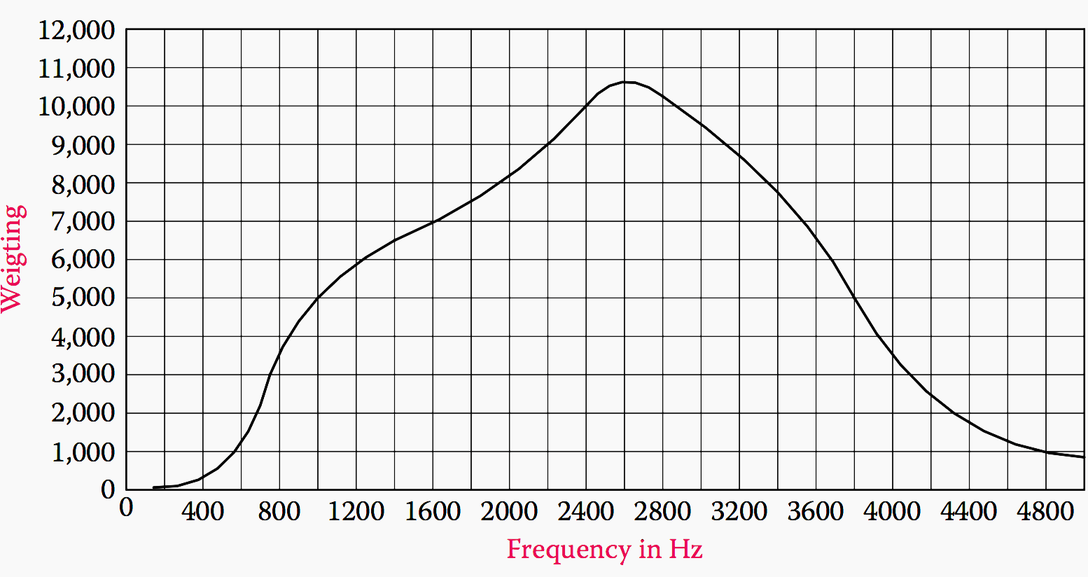
8. Communication Systems Interference
Communication systems are susceptible to interference from harmonics, particularly those that result in frequencies in the audible range. Any increase in audible telephone interference needs to be investigated, since this is often the first warning that harmonics are present or are increasing.
The weighting in the W factor is based on the sensitivity of the human ear and is shown in figure 4. The communication interference due to inductive coupling between power and communication circuits is calculated using the TIF, which is de ned as:

Where:
Wf = 5 × Pf × f
Where:
- Vf is rms voltage at frequency f
- Wf is TIF weightage factor at frequency f
- Vt is rms fundamental
- Pf is C message weighting
- 5 is constant to simulate captive coupling
- f is frequency
Impact of Nonlinear Loads
Harmonics are a convenient way of expressing the waveform distortion caused by nonlinear loads in electrical power systems. Before the introduction of power electronics, most nonlinear loads were the result of static rectifier systems or the operation of transformers of shunt reactors at voltages beyond their magnetizing knee point, i.e., beyond their linear region.
Since the introduction of power electronics into industrial systems, waveform distortion has become more common, and the need for analysis of the resultant harmonics has increased.
To control the level of harmonics in any system, it is important to know both the source of harmonics and the devices that are sensitive to such harmonics to limit their effect in any network.
Table 1 – Harmonic current generated by nonlinear loads (% of Fundamental)
| Harmonic Order | Rectifier 6/12-Pulse | VFD PWM6-Pulse | SMPS | PC | Fluoroscent Lamps |
| 3 | … | … | 81 | 57 | 28.7 |
| 5 | 20/… | 25-47 | 60.6 | 38 | 2.6 |
| 7 | 14.3/… | 16 | 37.5 | 23 | 2.2 |
| 9 | … | … | 15.7 | 13 | … |
| 11 | 9.1/9.1 | 8.7 | 2.4 | 23 | … |
| 13 | 7.7/7.7 | 4.5 | 6.3 | 5 | … |
| 15 | … | … | 7.9 | 3 | … |
| 17 | 5.9/… | 3.7 | … | … | … |
| 19 | 5.3/… | 1.9 | … | … | … |
| THD | 28/14.3 | 51 | 116 | 75 | 29 |
Reference // Industrial power systems by Shoaib Khan (Get hardcover from Amazon)
Related electrical guides & articles


Edvard Csanyi
Hi, I'm an electrical engineer, programmer and founder of EEP - Electrical Engineering Portal. I worked twelve years at Schneider Electric in the position of technical support for low- and medium-voltage projects and the design of busbar trunking systems.I'm highly specialized in the design of LV/MV switchgear and low-voltage, high-power busbar trunking (<6300A) in substations, commercial buildings and industry facilities. I'm also a professional in AutoCAD programming.
Profile: Edvard Csanyi

Many errors and omissions !
hi Edvard, I just want to say thank you veryy much, now I understand why 5th – 7th order harmonics in the stator windings will produce 5th harmonic current in the stator, because most commercial AC drivers use 6 pulse rectifier, while 12 pulse rectifier will produce 11th – 13th order hermonic current, thank you once again.
Excellent site, just so much information and really easy to understand and put into practice.
Thanks very much,
Dear Edward,
Your vast varieties of articles and the illustrated explanations in each of the topics has made this portal as the default go to site for me. Excellent work man..
Thank you Arjun, that’s very kind of you.
My congratulations on your article, I have experienced some of those issues in my active working days. Once again Congratulations. Thanks & Regards
HELLO SIR,
YOUR SITE IS BECOME MY TEXTBOOK FOR UNDERSTANDING THING.
GREAT AND WORTHY WORK.
THANK U SO MUCH.
Muy interesante el articulo, aprecio el esfuerzo que pones en escribir cada uno de ellos
Saludos de un venezolano que siempre lee estos interesantes articulos !
// Is interesting article, I appreciate a lot the time and effort that you employ in write this
a greeting from a venezuelan that always read your interesting articles!
Important subject about harmonics in electrical systeme and it cause/effects.
PLEASE SEND ME LIMITS THDI% FOR DRIVES FOR ELEVATORS
Dear Edward Csanyi,
Good Morning,
Your Articles are very nice. It is very useful to gain vast knowledge in Electrical Engg. My humble request is , if time allowed to you, kindly publish articles on Motor Bearings also.
Thanks & Regards
Jagadish Gampa