
Household Circuit Wirings
The circuit wirings in this article show the most common wiring variations for typical electrical devices. Most new wiring you install will match one or more of the wirings shown. Find the wirings that match your situation and use them to plan your circuit layouts. Since the number of variations exceeds 30, I decided to split this technical article into three parts.
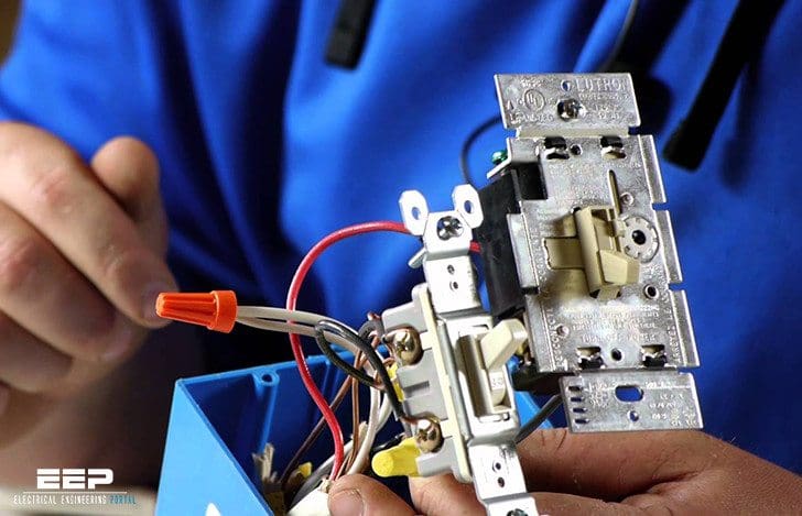 31 Common Household Circuit Wirings You Can Use For Your Home (photo credit: smartthings.com)
The 120 V circuits shown below are wired for 15 A using 14-gauge wire and receptacles rated at 15 A. If you are installing a 20 A circuit, substitute 12-gauge cables and use receptacles rated for 15 or 20 A.
In configurations where a white wire serves as a hot wire instead of a neutral, both ends of the wire are coded with black tape to identify it as hot. In addition, each of the circuit wirings shows a box grounding screw. This grounding screw is required in all metal boxes, but plastic electrical boxes do not need to be grounded.
You should remember two new code requirements when wiring switches.
- Provide a neutral wire at every switch box. This may require using a 3-wire cable or two 2-wire cables where you may have used one 2-wire cable in the past.
- Use a black or red wire to supply power from a switch to a light or switched receptacle.
Note: For clarity, all grounding conductors in the circuit wirings are colored green. In practice, the grounding wires inside sheathed cables usually are bare copper.
1st part | 2nd part | 3rd part
The list of first 10 wiring circuits:
- 120V duplex receptacles wired in sequence
- GFCI receptacles (single-location protection)
- GFCI receptacle, switch & light fixture (wired for multiple-location protection)
- Single-pole switch and light fixture (light fixture at end of cable run)
- Single-pole switch and light fixture (switch at end of cable run)
- Single-pole switch and two light fixtures (switch between light fixtures, light at start of cable run)
- Single-pole switch & light fixture, duplex receptacle (switch at start of cable run)
- Switch-controlled split receptacle, duplex receptacle (switch at start of cable run)
- Switch-controlled split receptacle (switch at end of cable run)
- Switch-controlled split receptacle, duplex receptacle (split receptacle at start of run)
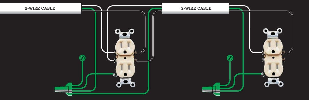
1. 120V duplex receptacles wired in sequence

Use this layout to link any number of duplex receptacles in a basic lighting / receptacle circuit. The last receptacle in the cable run is connected like the receptacle shown at the right side of the circuit wiring below. All other receptacles are wired like the receptacle shown on the left side.
This configuration or layout requires two-wire cables.
2. GFCI receptacles (single-location protection)
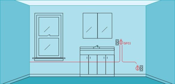
Use this layout when receptacles are within 6 ft. of a water source, such as those in kitchens and bathrooms. To prevent nuisance tripping caused by normal power surges, GFCIs should be connected only at the line screw terminal so they protect a single location, not the fixtures on the load side of the circuit. Requires two-wire cables.
Where a GFCI must protect other fixtures, use circuit wiring 3. Remember that bathroom receptacles should usually be on a dedicated 20 A circuit and that all bathroom receptacles must be GFCI-protected.
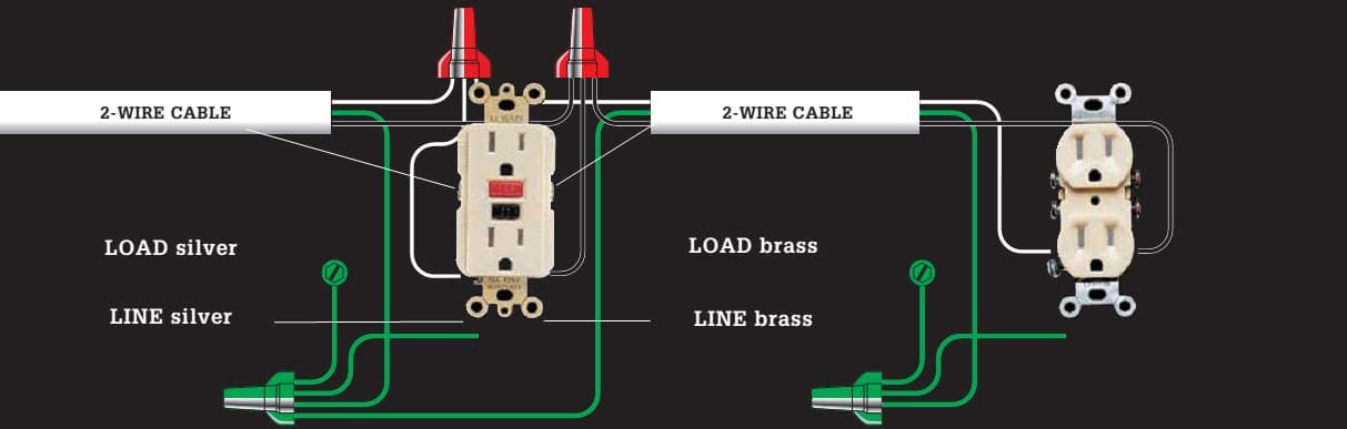
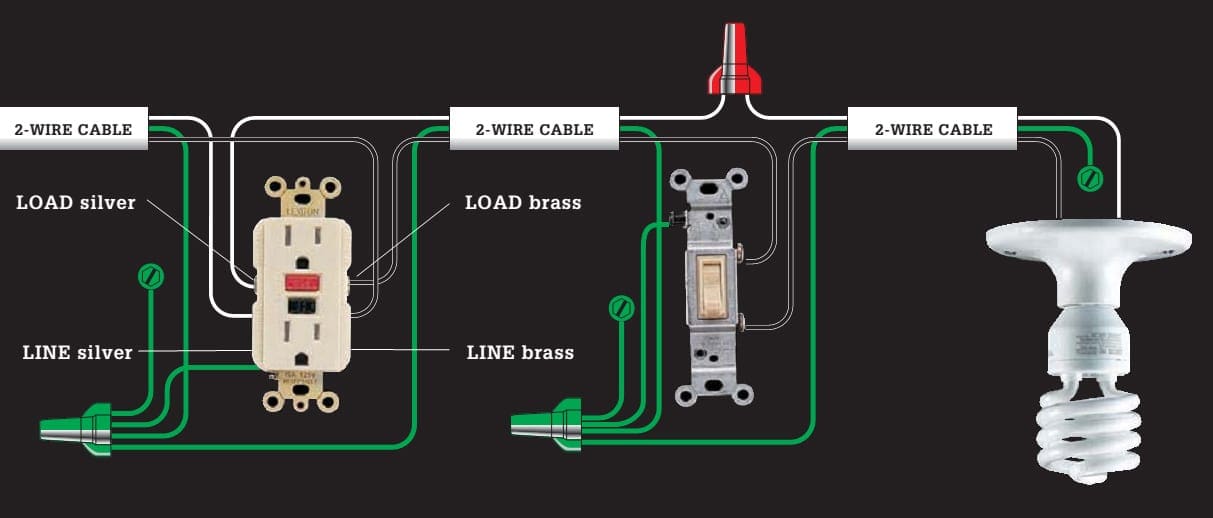
3. GFCI receptacle, switch & light fixture (wired for multiple-location protection)
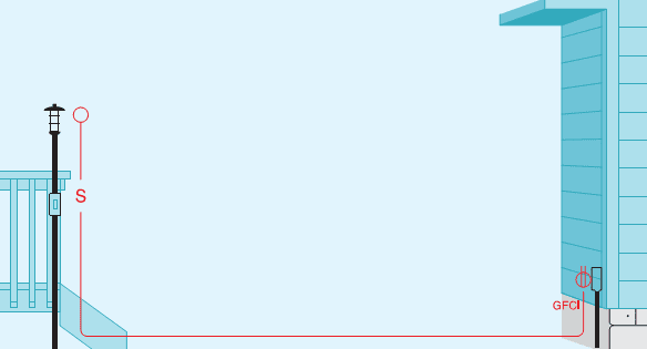
In some locations, such as an outdoor circuit, it is a good idea to connect a GFCI receptacle, so it also provides shock protection to the wires and fixtures that continue to the end of the circuit. Wires from the power source are connected to the line screw terminals. Outgoing wires are connected to load screws.
Requires two-wire cables.
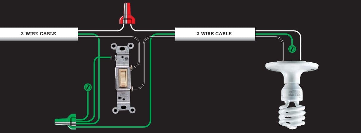
4. Single-pole switch and light fixture (light fixture at end of cable run)
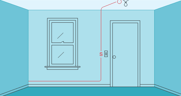
Use this layout for light fixtures in basic lighting / receptacle circuits throughout the home. It is often used as an extension to a series of receptacles (circuit wiring 1). Requires two-wire cables.
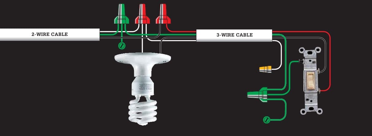
5. Single-pole switch and light fixture (switch at end of cable run)

Use this layout, sometimes called a switch loop, where it is more practical to locate a switch at the end of the cable run. In the last length 3-wire cable is used to make a hot conductor available in each direction. Requires two-wire and three-wire cables.
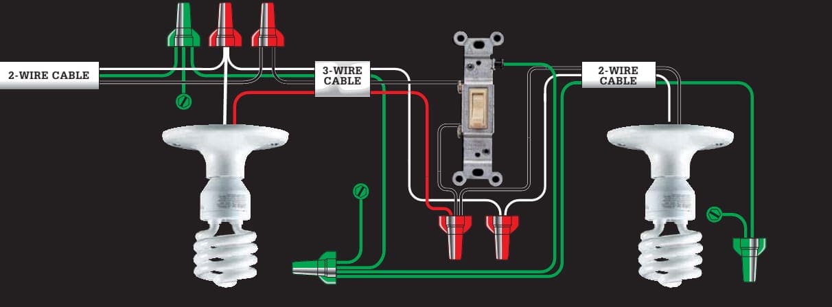
6. Single-pole switch and two light fixtures (switch between light fixtures, light at start of cable run)
Use this layout when you need to control two fixtures from one single-pole switch and the switch is between the two lights in the cable run. Power feeds to one of the lights. Requires two-wire and three-wire cables.
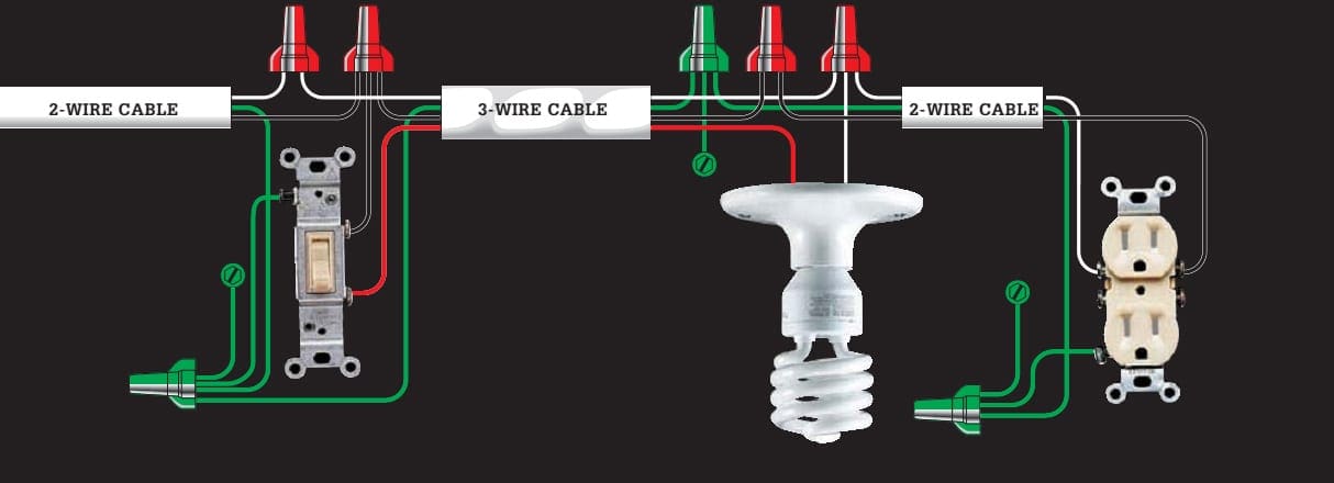
7. Single-pole switch & light fixture, duplex receptacle (switch at start of cable run)

Use this layout to continue a circuit past a switched light fixture to one or more duplex receptacles. To add multiple receptacles to the circuit, see circuit wiring 1. Requires two-wire and three-wire cables.
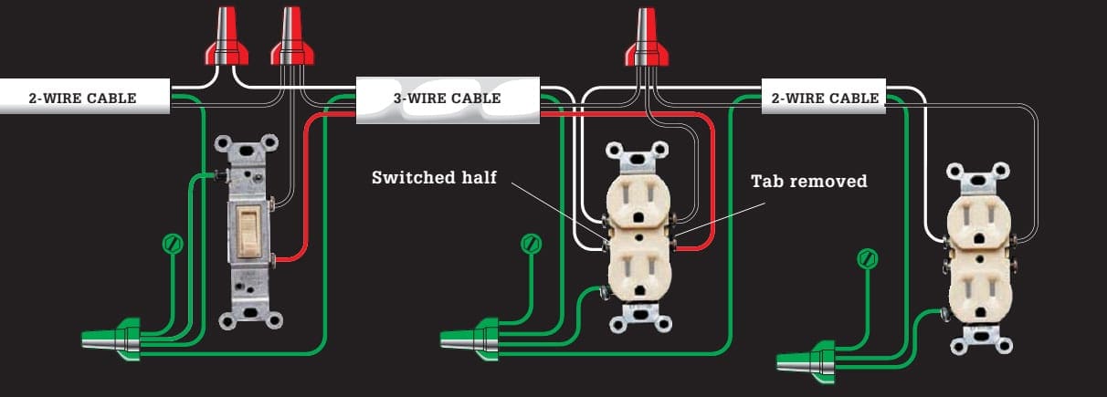
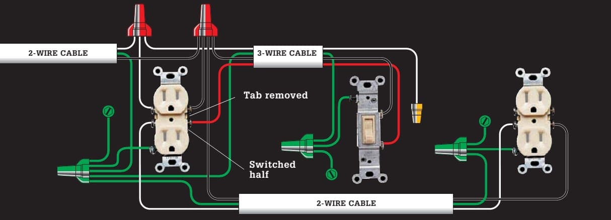
8. Switch-controlled split receptacle, duplex receptacle (switch at start of cable run)
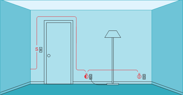
This layout lets you use a wall switch to control a lamp plugged into a wall receptacle. This configuration is required by code for any room that does not have a switch-controlled wall or ceiling fixture. Only the bottom half of the first receptacle is controlled by the wall switch.
The top half of the receptacle and all additional receptacles on the circuit are always hot. Requires two-wire and three-wire cables.
Some electricians help people identify switched receptacles by installing them upside down.
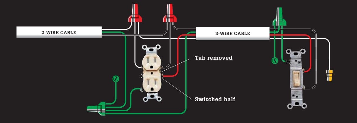
9. Switch-controlled split receptacle (switch at end of cable run)
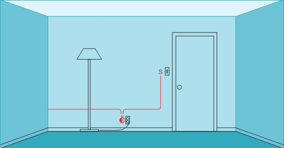
Use this switch loop layout to control a split receptacle (see circuit wiring 7) from an end-of-run circuit location. The bottom half of the receptacle is controlled by the wall switch, while the top half is always hot. Requires two-wire and three-wire cable.
Some electricians help people identify switched receptacles by installing them upside down.
10. Switch-controlled split receptacle, duplex receptacle (split receptacle at start of run)

Use this variation of circuit wiring 7 where it is more practical to locate a switch-controlled receptacle at the start of a cable run. Only the bottom half of the first receptacle is controlled by the wall switch. The top half of the receptacle, and all other receptacles on the circuit, are always hot. Requires two-wire and three wire cables.
Some electricians help people identify switched receptacles by installing them upside down.
1st part | 2nd part | 3rd part
Reference // The Complete Guide to Electrical Wiring (Current with 2014–2017 Electrical Codes) – Black+Decker


Am ezra kessio and i whan to be electrical engineering and to learn more about electricity
Actually, this is a great article. I actually really appreciate the creative trends you’re putting out here.
Good content
Amazing topic
i like it