
Estimated Study Time: 4 minutes
Content
- Visual and Mechanical Inspection
- Electrical Tests
- Test Values
- TABLE 100.12 – US Standard Fasteners – Bolt-Torque Values for Electrical Connections
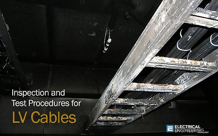
Cables, Low-Voltage, 600 Volt Maximum
1. Visual and Mechanical Inspection
- Compare cable data with drawings and specifications.
- Inspect exposed sections of cables for physical damage and correct connection in accordance with single-line diagram.
- Inspect bolted electrical connections for high resistance using one of the following methods:
- Use of low-resistance ohmmeter in accordance with previous Section 1.2.
- Verify tightness of accessible bolted electrical connections by calibrated torque-wrench method in accordance with manufacturer’s published data or Table 100.12.
- Perform thermographic survey:
- Perform thermographic survey when load is applied to the system
- Remove all necessary covers prior to thermographic inspection. Use appropriate caution, safety devices, and personal protective equipment
- Perform a follow-up thermographic survey within 12 months of final acceptance by the owner
- Inspect compression-applied connectors for correct cable match and indentation.
- Inspect for correct identification and arrangements.
- Inspect jacket insulation and condition.
2. Electrical Tests
- Perform resistance measurements through bolted connections with low-resistance ohmmeter.
- Perform insulation-resistance test on each conductor with respect to ground and adjacent conductors. Applied potential shall be 500 volts DC for 300 volt rated cable and 1000 volts DC for 600 volt rated cable. Test duration shall be one minute.
- Perform continuity tests to insure correct cable connection.
- Verify uniform resistance of parallel conductors.
3. Test Values
- Compare bolted connection resistances to values of similar connections.
- Bolt-torque levels should be in accordance with Table 100.12 unless otherwise specified by the manufacturer.
- Microhm or millivolt drop values shall not exceed the high levels of the normal range as indicated in the manufacturer’s published data. If manufacturer’s datais not available, investigate any values which deviate from similar connections by more than 50 percent of the lowest value.
- Insulation-resistance values should not be less than 50 megohms.
- Investigate deviations in resistance between parallel conductors.
TABLE 100.12
US Standard Fasteners – Bolt-Torque Values for Electrical Connections


a. Consult manufacturer for equipment supplied with metric fasteners.
b. This table is based on bronze alloy bolts having a minimum tensile strength of 70,000 pounds per square inch.
c. This table is based on aluminum alloy bolts having a minimum tensile strength of 55,000 pounds per square inch.
d. This table is to be used for the following hardware types:
- Bolts, cap screws, nuts, flat washers, locknuts (18–8 alloy)
- Belleville washers (302 alloy).
Resource: Acceptance Testing Specifications for Electrical Power Distribution Equipment and Systems – NETA 2003
Related electrical guides & articles


Edvard Csanyi
Hi, I'm an electrical engineer, programmer and founder of EEP - Electrical Engineering Portal. I worked twelve years at Schneider Electric in the position of technical support for low- and medium-voltage projects and the design of busbar trunking systems.I'm highly specialized in the design of LV/MV switchgear and low-voltage, high-power busbar trunking (<6300A) in substations, commercial buildings and industry facilities. I'm also a professional in AutoCAD programming.
Profile: Edvard Csanyi

Hi, I’m not an electrical engineer and do not hold any electrical training, please be gentle with your answers so I can understand. A question that’s bugged me for some time when completing fit out projects, could a experienced electrical engineer highlight a unterminated 240v cable when completing their commissioning and testing? So this would be a open ended live 240v cable coiled and unused dangling within a new ceiling void perhaps?
what are the mechanical testing parameters for silicon insulated cables? and how to check.?
I curious as to why the torque values are so vastly different from any torque charts I have found elswhere. Example; most places I find a value of 30-35ft/lbs for 3/8 grade 5 hardware and here it is 20ft/lbs.
Thanks
Hello Edvard,
Can you please share me some standard name or some reference, supporting your point on “Applied potential shall be 500 volts DC for 300 volt rated cable and 1000 volts DC for 600 volt rated cable.”
Would be very grateful to you!
Thanks, and Cheers!
Within the UK, BS 7671 is the standard to which you should refer, there are also useful guidance notes avIlable from the IET on inspection. Elsewhere in. Europe, you should look to test and inspect in accordance with IEC 60364.
Thermographic testing is not something i would necessarily expect, i have not seen this done on cables in 30 years of working in this industry. Thermographic tests on switchgear, controlgear and bus-duct joints by all means. If you are leaving covers open/off as per edwards suggestion then precautions are. Obviously necessary to prevent contact with live parts.
I would be more concerned with cable terminations, therefore a torque wrench applied to the cable joints would be a good check to add.
Also check that the installation method is as per the design calculations and methodology etc
Dear Edward,
Question: what is the acceptance resistance of low voltage cables? Can u send me and answer of this question please…thanks!
Dear Edward, since you are specialized in the designing of the LV bus ducts, in our installation of 5000 Amps bus-bar connected between transformer and PCC panel. with the loading of 70 % current (i.e. 3500 Amps) we observed that there is excessive humming coming from the bus-duct. Also heat is observed at the top end of the vertical end of the bus-duct.
Please suggest possible checks that can be performed to avoid any breakdown
Humming is produced by bus duct itself and if it is already tighten not to move a 1mm – there is nothing you can do, except to send your claim to manufacturer. There is something inside bus duct that vibrates and if customer does not complain I suggest you just to send question to manufacturer asking what to do.
In order to define heat at the top of bus duct you must perform thermal-vision testing with infrared camera during highest load. Did you see any visual change in bus duct color? If so, this is not good, but if the color is same everywhere there is no room for panic.
Thank You :)
Thanks for all
thanks