Continued from 2nd part: Lighting Circuits Connections for Interior Electrical Installations (2)
Emergency lighting circuits
The main reason for installing an emergency lighting system is to enable the building to meet fire safety legislation in a way that is visually acceptable and meets the user’s needs for ease of operation and maintenance.
Consequently it is important to establish all the relevant legal requirements for emergency lighting and fire alarm systems before commencing the design these should ideally be agreed between the system designer, user, fire authority, building control officer and system installer.
Wiring of emergency lighting system, two circuits A.C./D.C. interconnection
Description:
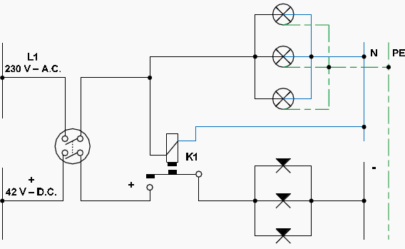
The following wiring has two circuits, one A.C. 230 V and one D.C. of 24V or 42 V, respectively with appropriate lights. Constitutes one of the most common emergency lighting circuits for places that we want to avoid panic in case of power failure.
When there is voltage on the grid, the relay opens the backup circuit contacts and when the grid voltage is interrupted the relay closes his backup circuit contacts.
General diagrams
Operating diagram:

Important note:
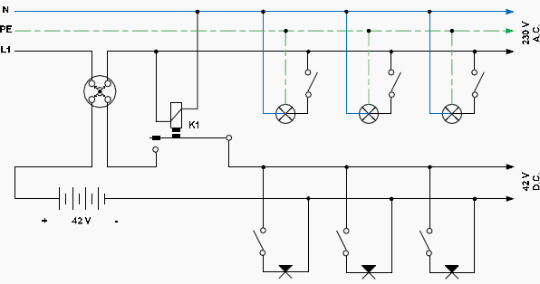
The relay is controlled by the A.C. circuit while the D.C. circuit is supplied through the contact K1: 13 – 14. In the same sense, we can supply the D.C. circuit through another relay’s main contacts (e.g. K3: 1 – 2), to be controlled by the contact K1: 13 – 14.
The emergency lighting is less powerful than the main lighting of the building and is composed by independent lamps or/and with some of the lamps of the main lighting circuit. On the premises that emergency lighting is required the voltage source is a battery bank, usually with 24 V or 42 V voltage level. The lamps provided for respective operating voltage.
The array of the batteries according to the loads provided to supply, consists of one or more battery banks. In each group the batteries are connected in series to aggregate the required voltage.
Analytical diagram:

Important note:
If a central battery DC supply system is used for the Emergency Lighting System, it shall be operated at a normal battery voltage of not less than 24 V and not more than 120 V D.C. from a common bank.
UPS (Uninterruptible Power Supply) based emergency lighting system
In new facilities and in cases requiring continuous supply of electrical power and/or constant voltage and/or constant frequency, units of Uninterruptible Power Supply (UPS) are used.
These units are inserted between the supply and the load.
If utility power is interrupted or falls outside specific parameters, the UPS uses a backup battery supply to maintain power to the critical load (in our case the emergency lighting system) for a specified period of time or until the utility power returns.
For extended power outages, the UPS allows you to either transfer to an alternative power system (such as a generator) or shut down your critical load in an orderly manner.

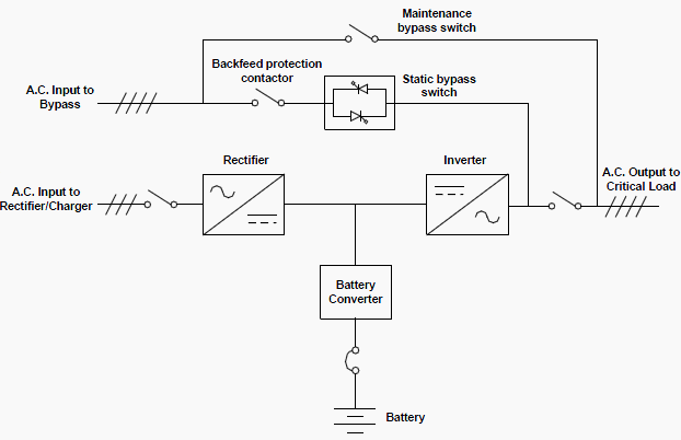
The emergency lighting circuit is connected to the A.C. output of the UPS (whether single phase or three phase), as we saw in the previous circuits.
The backfeed protection contactor is located in series with the static switch. For manual transfers to bypass, the static switch is also used. The static switch is armed and ready during both types of transfers.
The UPS systems are distinguished by their electrical power in to main categories:
1. Low power UPS
Single phase UPS, with effect from 300VA to 10 KVA , used for the protection of personal computers, small and medium sized computer networks (servers), telecommunications equipment and security systems (e.g. emergency lighting, alarm systems, fire detection and extinguishing systems).
2. High power UPS
With three phase input and either a single phase output with effect from 5 KVA to 80 KVA or with a three phase output with effect from 80 KVA to 800 KVA.
References:
- Andreas Goutis, ‘Electrical drawing, Part 1’
- EATON Powerware UPS ‘Installation and Operation Manual’
- DSPM INC. ‘Digital Signal Power Manufacturer’


