
Earth resistance of an earth electrode
When an earth electrode system has been designed and installed, it is usually necessary to measure and confirm the earth resistance between the electrode and “true Earth”. The most commonly used method of measuring the earth resistance of an earth electrode is the 3-point measuring technique shown in Figure 1.
 The most common methods of measuring the resistance of an earth electrode
This method is derived from the 4-point method, which is used for soil resistivity measurements.
The 3-point method, called the “fall of potential” method, comprises the Earth Electrode to be measured and two other electrically independent test electrodes, usually labelled P (Potential) and C (Current). These test electrodes can be of lesser “quality” (higher earth resistance) but must be electrically independent of the electrode to be measured.
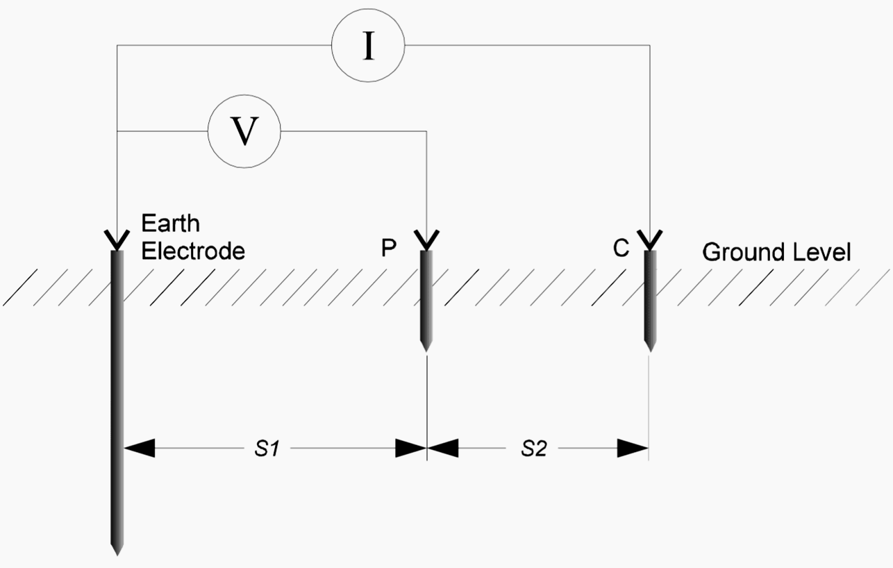
An alternating current (I) is passed through the outer electrode C and the voltage is measured, by means of an inner electrode P, at some intermediary point between them.
The Earth Resistance is simply calculated using Ohm’s Law: Rg = V/I.
Other more complex methods, such as the Slope Method or the Four Pole Method, have been developed to overcome specific problems associated with this simpler procedure, mainly for measurements of the resistance of large earthing systems or at sites where space for locating the test electrodes is restricted.
When performing a measurement, the aim is to position the auxiliary test electrode C far enough away from the earth electrode under test so that the auxiliary test electrode P will lie outside the effective resistance areas of both the earth system and the other test electrode (see Figure 2).
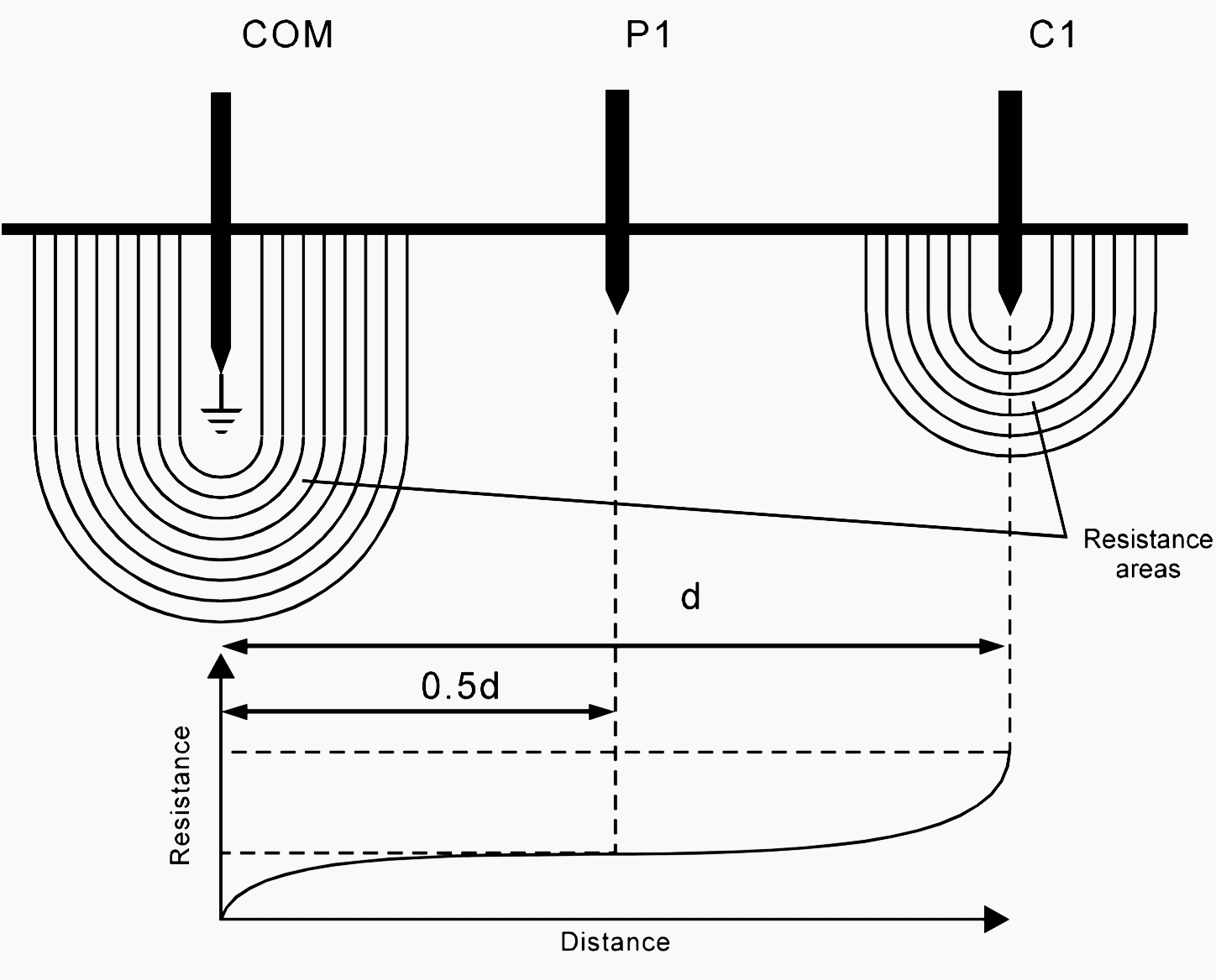
- If the current test electrode, C, is too close, the resistance areas will overlap and there will be a steep variation in the measured resistance as the voltage test electrode is moved.
- If the current test electrode is correctly positioned, there will be a ‘flat’ (or very nearly so) resistance area somewhere in between it and the earth system, and variations in the position of the voltage test electrode should only produce very minor changes in the resistance figure.
The instrument is connected to the earth system under test via a short length of test cable, and a measurement is taken.
Often it is difficult to judge, merely from visual inspection of the site, a suitable location for the tests stakes and so it is always advisable to perform more than one measurement to ensure the accuracy of the test.
Fall of Potential Method
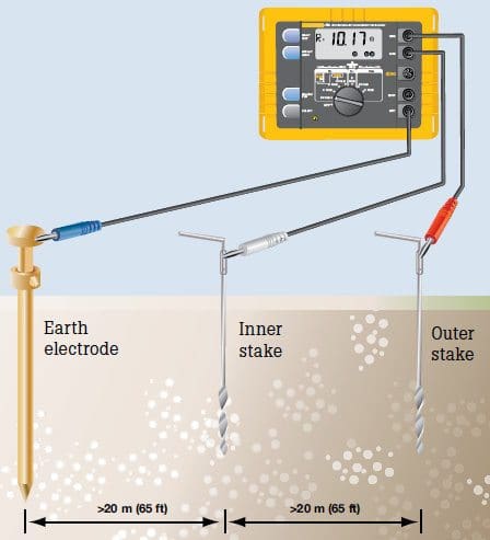
This is one of the most common methods employed for the measurement of earth resistance and is best suited to small systems that don’t cover a wide area. It is simple to carry out and requires a minimal amount of calculation to obtain a result.
This method is generally not suited to large earthing installations, as the stake separations needed to ensure an accurate measurement can be excessive, requiring the use of very long test leads (refer to Table 1).
Normally, the outer test electrode, or current test stake, is driven into the ground 30 to 50 metres away from the earth system, (although this distance will depend on the size of the system being tested – refer to Table 1) and the inner electrode, or voltage test stake, is then driven into the ground mid-way between the earth electrode and the current test stake, and in a direct line between them.
Table 1 – Variation of current and voltage electrode separation with maximum earth system dimensions, in metres
| Maximum dimension across earth system | Distance from ‘electricalcentre’ of earth system to voltage test stake | Minimum distance from ‘electrical centre’ of earth system to current test stake |
| 1 | 15 | 30 |
| 2 | 20 | 40 |
| 5 | 30 | 60 |
| 10 | 43 | 85 |
| 20 | 60 | 120 |
| 50 | 100 | 200 |
| 100 | 140 | 280 |
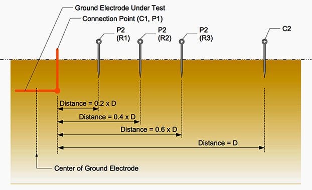
The Fall of Potential method incorporates a check to ensure that the test electrodes are indeed positioned far enough away for a correct reading to be obtained. It is advisable that this check be carried, as it is really the only way of ensuring a correct result.
To perform a check on the resistance figure, two additional measurements should be made:
- The first with the voltage test electrode (P) moved 10% of the original voltage electrode-to-earth system separation away from its initial position, and
- The second with it moved a distance of 10% closer than its original position, as shown in Figure 3.

If these two additional measurements are in agreement with the original measurement, within the required level of accuracy, then the test stakes have been correctly positioned and the DC resistance figure can be obtained by averaging the three results.
The stakes should be repositioned at a larger separation distance or in a different direction and the three measurements repeated. This process should be repeated until a satisfactory result is achieved.
The 62% Method
The Fall of Potential method can be adapted slightly for use with medium sized earthing systems. This adaptation is often referred to as the 62% Method, as it involves positioning the inner test stake at 62% of the earth electrode-to-outer stake separation (recall that in the Fall-of-Potential method, this figure was 50%).
All the other requirements of test stake location – that they be in a straight line and be positioned away from other structures – remain valid.
When using this method, it is also advisable to repeat the measurements with the inner test stake moved ±10% of the earth electrode-inner test stake separation distance, as before.
The main disadvantage with this method is that the theory on which it is based relies on the assumption that the underlying soil is homogeneous, which in practice is rarely the case. Thus, care should be taken in its use and a soil resistivity survey should always be carried out.
Alternatively, one of the other methods should be employed.
Other Test Methods
Many other methods exist for taking earth resistance measurements. Many of these methods have been designed in an attempt to alleviate the necessity for excessive electrode separations, when measuring large earth systems, or the requirement of having to know the electrical centre of the system.
Three such methods are briefly described below. Specific details are not given here, but instead the reader is referred to the relevant technical paper where these systems are described in detail.
- The slope method
- The star-delta method
- The four-potential method (Wenner method)
(a) The Slope Method
This method is suitable for use with large earthing systems, such as power substation earths. It involves taking a number of resistance measurements at various earth system to voltage electrode separations and then plotting a curve of the resistance variation between the earth and the current.
The additional measurement and calculation effort tends to relegate this system to use with only very large or complex earthing systems.
For full details of this method, refer to paper 62975, written by Dr G.F. Tagg, taken from the proceedings of IEE volume 117, No 11, Nov. 1970.
NETA WORLD TechTips ‘Slope Method’ by by Jeff Jowett AVO International:
(b) The Star-Delta Method
This technique is well suited to use with large systems in built up areas or on rocky terrain, where it may be difficult to find suitable locations for the test electrodes, particularly over long distances in a straight line.
Using these results, a number of calculations are performed and a result can be obtained for the resistance of the earth system. This method, developed by W. Hymers, is described in detail in Electrical Review, January 1975.
NETA WORLD TechTips ‘Ground Testing in Difficult Installations’ by Jeffrey R. Jowett (Megger):
(c) The Four Potential Method (Wenner method)
This technique, helps overcome some of the problems associated with the requirement for knowing the electrical centre of the earthing systems being tested.
The main draw back with the Four Potential method is that, like with the Fall of Potential method, it can require excessive electrode separation distances if the earthing system being measured is large.
NETA WORLD TechTips ‘Ground Resistance Testing: Four Potential Method’ by Jeffrey R. Jowett (Megger):
Reference // Earthing Techniques by Lightning & Surge Technologies


What is the effect of conducting earth resistance test in a 132KV Energized substation?
What is the meaning of the symbol Rg?
You’re highly appreciated🙏
Engr. Edvard Csanyi
Thanks, Edvard that helps me a lot to clear basic understanding.
That white paper has cleared many doubts in my mind.
Please update this article if you got any extra resources related to the same topic.
Estimado Edvard
Excelente e ilustrativa su capacitación.
Gracias.
very useful this lessons for me as a electrical technician.we can clearly understand it.thanks mr.edvard (EEP)
Thanks
Extremely useful
thanks alot for your effort in these web site, i`ve found him very useful for engineers that is gave basic information ,i hope to see in future another contribution about settings of protection relays .