
Estimated Study Time: 8 minutes
Unbalance Protection
Unbalance in the supply voltage is typically due to a broken phase condition somewhere in the upstream network. This may result from single-phase fuse failure or pole discrepancy of a circuit breaker or a disconnector.
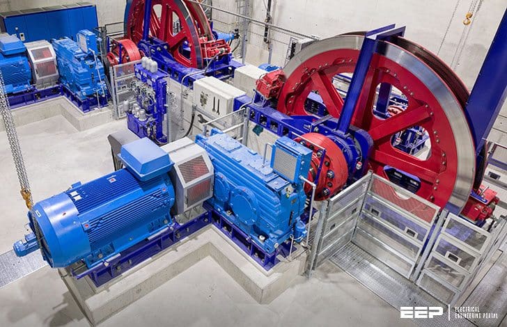 Protecting Motor From External Network Disturbances (Unbalance, V/Hz-ratio and Re-Energizing) (photo credit: ABB)
In addition, unequal loading of the phases causes unequal voltage drops, and thus a slight unbalance in the supply voltage may result. Unsymmetrical faults are causes of short-term unbalance conditions.
Unbalanced phase currents are a source of negative-sequence current in the motor, generating a magnetic flux component rotating in the opposite direction compared to the rotation direction of the motor shaft. The frequency of this flux component is 2-s, where s is the slip frequency in p.u, and it induces currents of this frequency in the rotor.
Thus, one unit of negative-sequence current causes higher heating effect than one unit of positive-sequence current.
NOTE: The current distribution between the phases depends on the cause and nature of the unbalance and on the motor characteristics.
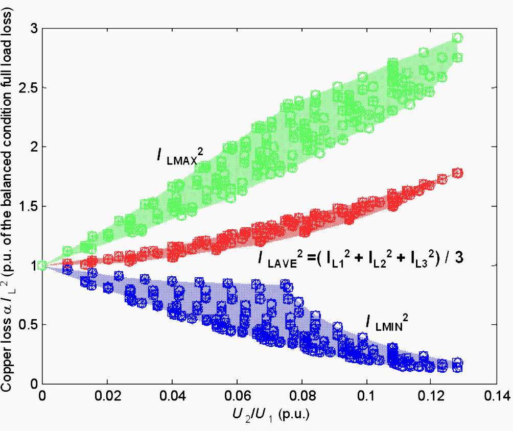
Figure 1 shows an example how the motor loss is increased as the supply voltage and as a result, the phase currents become unbalanced. It has been assumed that the loss is directly proportional to IL2 and the skin effect has been neglected (IL is the phase current). In addition, the calculation of the average loss assumes perfect thermal conductivity between the phases.
The results in Figure 1 have been calculated by varying the amplitude and phase angle of each phase voltage in turn.
Considering the above, a separate unbalance protection is required to protect the motor running with unbalanced supply voltage unless the heating effect of the negative-sequence current has been adequately taken into account by the thermal model used in the overload protection.
Unbalance also causes mechanical problems like vibration. Therefore, at least severe unbalance should always be detected, and a dedicated unbalance protection based on, for example,the magnitude of the negative-sequence current, is recommended.
Inverse time characteristic should be preferred and the operation time should be selected so that the normal use of the motor is allowed, especially the starting of the machine, when in practice some negative- sequence current may be measured.
Variation in Supply Voltage and Frequency
In most cases, motors can be approximated as volt-independent loads with constant V/Hz-ratio: A decrease in the supply voltage will be followed by an increase in the phase current. As long as the V/Hz-ratio is nearly at a constant level, the variations in voltage and frequency do not cause any specific harm for the motor.
In this case, undervoltage condition causes an increase in the phase current, and overloading of the motor may take place, which is then detected by the thermal overload protection.
Typically, protection against sustained undervoltage and overvoltage is arranged. This protection operates in case of overvoltage in the order of 10-20%. Undervoltage protection is set to trip in case of total loss of voltage, so that when the voltage returns, simultaneous restart of all the motors is prevented.
Out-of-Phase Re-Energizing Protection
Abnormally high starting current can be produced in a motor if energized shortly after a supply interruption. The resulting current can be higher than the normal starting current imposing to excessive thermal and mechanical stress, which may result in direct motor damage.
After the supply interruption, voltage and frequency measured from the motor terminals start to decay. This decay results in the phase angle, voltage and frequency difference between the source side and motor terminal voltages (US and UM, Figure 2). The rate of the decay depends on the motor type and drive characteristics.
An example of this is shown in Figure 2 below:
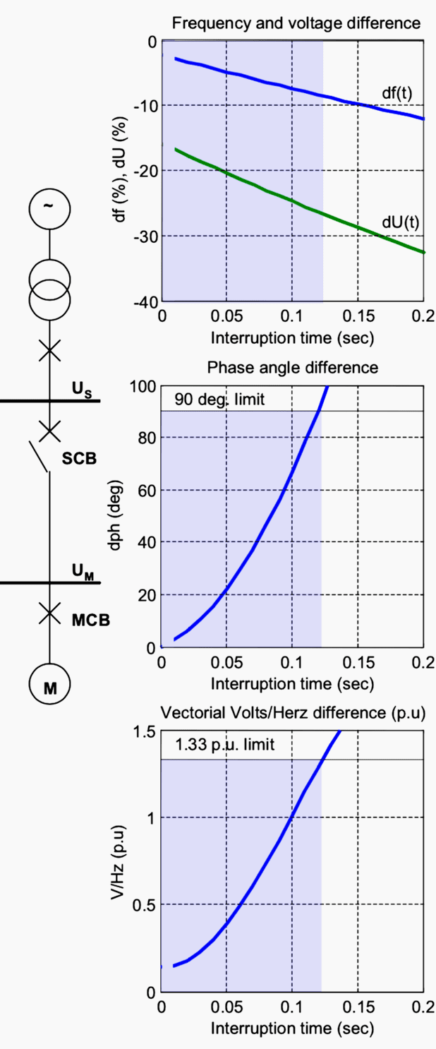
Whether a reclosing to a single source, that is, closing the source circuit breaker, SCB in Figure 2, can be done or not depends on how the magnitudes of the above difference quantities develop during the interruption and on the length of the interruption.
The example is based on the requirement that the resultant vectorial voltage difference in per unit volts per hertz on the motor rated voltage, and the frequency base must not exceed a value of 1.33 p.u (ANSI C50.41-2000) at the instant the reclose is completed.
In addition, the phase angle difference must not exceed 90° at the instant the reclose is completed. It can be concluded, for example, that this motor drive can tolerate short supply interruptions (< 0.1 second) such as a high-speed autoreclose in the incoming line.
However, in case of longer supply interruptions (up to a few seconds), this motor must be disconnected before the supply is restored to avoid the possibility of re-energizing in out-of- phase condition.
The detection of the loss-of-supply condition and the initiation of the tripping of the motor feeder circuit breaker, MCB in Figure 2, when required, typically undervoltage, underfrequency or loss-of-power functions, or a combination of these can be applied.
Reference // Distribution Automation Handbook – Motor Protection by ABB
Related electrical guides & articles


Edvard Csanyi
Hi, I'm an electrical engineer, programmer and founder of EEP - Electrical Engineering Portal. I worked twelve years at Schneider Electric in the position of technical support for low- and medium-voltage projects and the design of busbar trunking systems.I'm highly specialized in the design of LV/MV switchgear and low-voltage, high-power busbar trunking (<6300A) in substations, commercial buildings and industry facilities. I'm also a professional in AutoCAD programming.
Profile: Edvard Csanyi

I am Electrical supervisor
I am working in Seylan Bank PLC
I want study to the circuit breaker selection lesson. please send to the detail pdf.
Myself Amreen Bano, working on merchant ships as Electro-Technical- Officer(ETO).
Thanks to EEP team for keeping us updates related day to day electrical technology stuff.
it will be more helpful if possible to post about Electronic, Automation and Instrumentation stuff as well.
Thanks & warm regards
ETO Amreen Bano
I am Electrical Technician
I am working in international steel limited
So that is amazing calculations T/f connection and wonderful news