
Estimated Study Time: 20 minutes
Examples Of Power Supply Protection
As industrial operations processes and plants have become more complex and extensive, the requirement for improved reliability of electrical power supplies has also increased. The potential costs of outage time following a failure of the power supply to a plant have risen dramatically as well.
 Protection And Control Of Industrial Power Supply Systems (Relay Schemes And Settings) - on photo MiCOM protection relays
The protection and control of industrial power supply systems must be given careful attention. Many of the techniques that have been evolved for EHV power systems may be applied to lower voltage systems also, but typically on a reduced scale.
However, industrial systems have many special problems that have warranted individual attention and the development of specific solutions.
In other plants, the nature of the process allows production of a substantial quantity of electricity, perhaps allowing export of any surplus to the public supply system – at either at sub-transmission or distribution voltage levels. Plants that run generation in parallel with the public supply distribution network are often referred to as co-generation or embedded generation.
In this technical article, the following examples of protection & control of industrial power supply systems are considered:
- Fuse Co-ordination
- Grading of Fuses / MCCBs / Overcurrent Relays
- Protection of a Dual-Fed Substation
1. Fuse Co-ordination
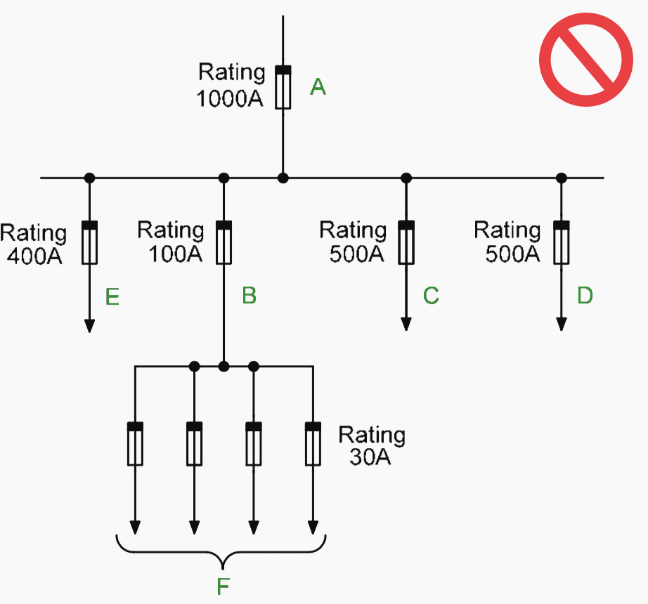
An example of the application of fuses is based on the arrangement in Figure 1(a). This shows an unsatisfactory scheme with commonly encountered shortcomings.
It can be seen that fuses B, C and D will discriminate with fuse A, but the 400A sub-circuit fuse E may not discriminate, with the 500A sub-circuit fuse D at higher levels of fault current.
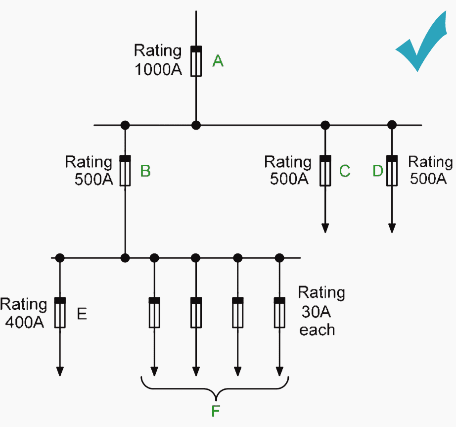
The solution, shown in Figure 1(b), is to feed the 400A circuit E direct from the busbars. The sub-circuit fuse D may now have its rating reduced from 500A to a value, of say 100A, appropriate to the remaining sub-circuit.
This arrangement now provides a discriminating fuse distribution scheme satisfactory for an industrial system.
However, there are industrial applications where discrimination is a secondary factor. In the application shown in Figure 2, a contactor having a fault rating of 20kA controls the load in one sub-circuit.
A fuse rating of 630A is selected for the minor fuse in the contactor circuit to give protection within the through-fault capacity of the contactor.
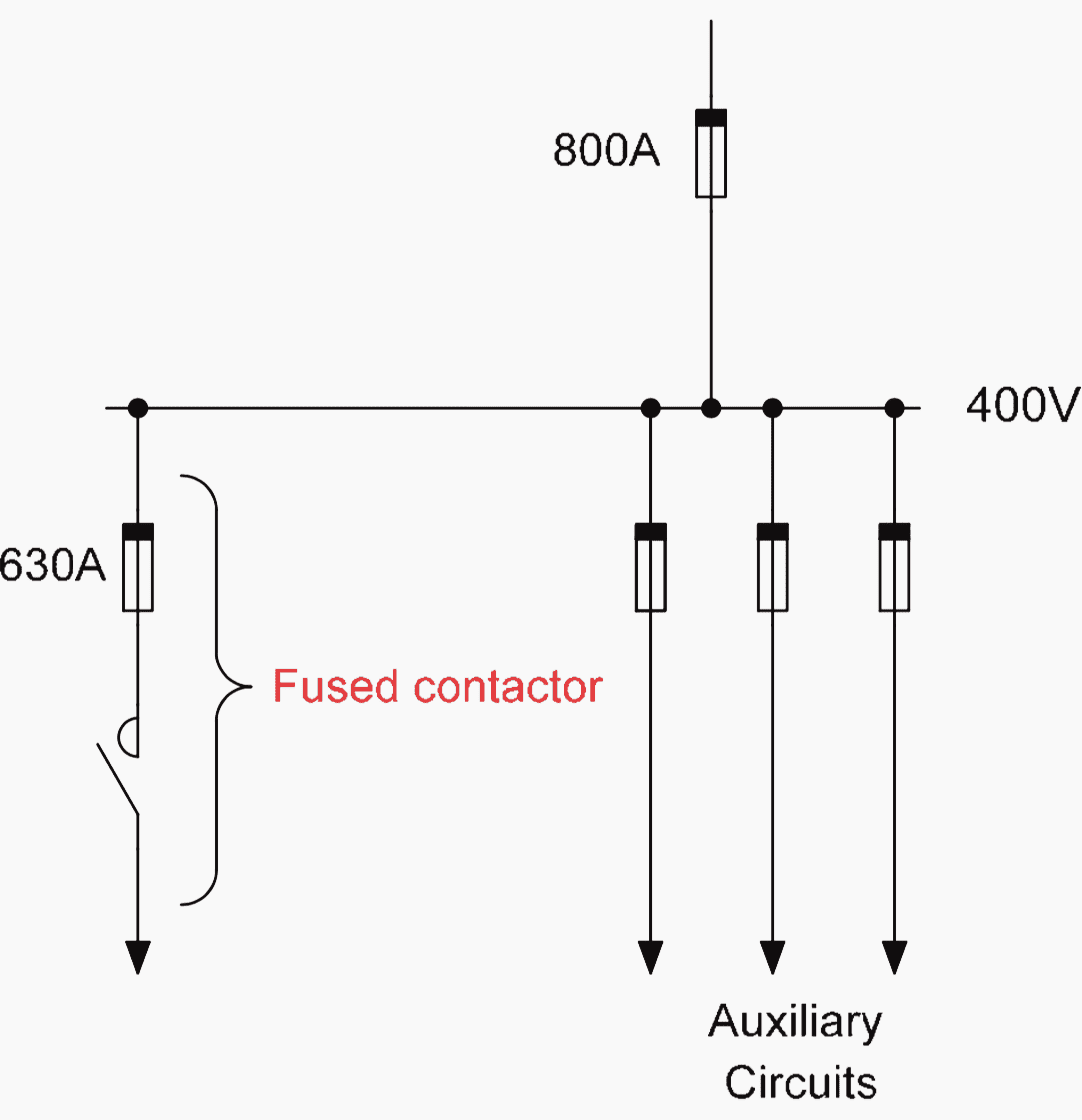
The major fuse of 800A is chosen, as the minimum rating that is greater than the total load current on the switchboard. Discrimination between the two fuses is not obtained, as the pre-arcing I2t of the 800A fuse is less than the total I2t of the 630A fuse.
This may be acceptable in some cases. In most cases, however, loss of the complete switchboard for a fault on a single outgoing circuit will not be acceptable, and the design will have to be revised.
2. Grading of Fuses / MCCBs / Overcurrent Relays
An example of an application involving a moulded case circuit breaker, fuse and a protection relay is shown in Figure 3.
A 1MVA 3.3kV/400V transformer feeds the LV board via a circuit breaker, which is equipped with an Alstom MiCOM P14x numerical relay having a setting range of 8-400% of rated current and fed from 2000/1A CTs.
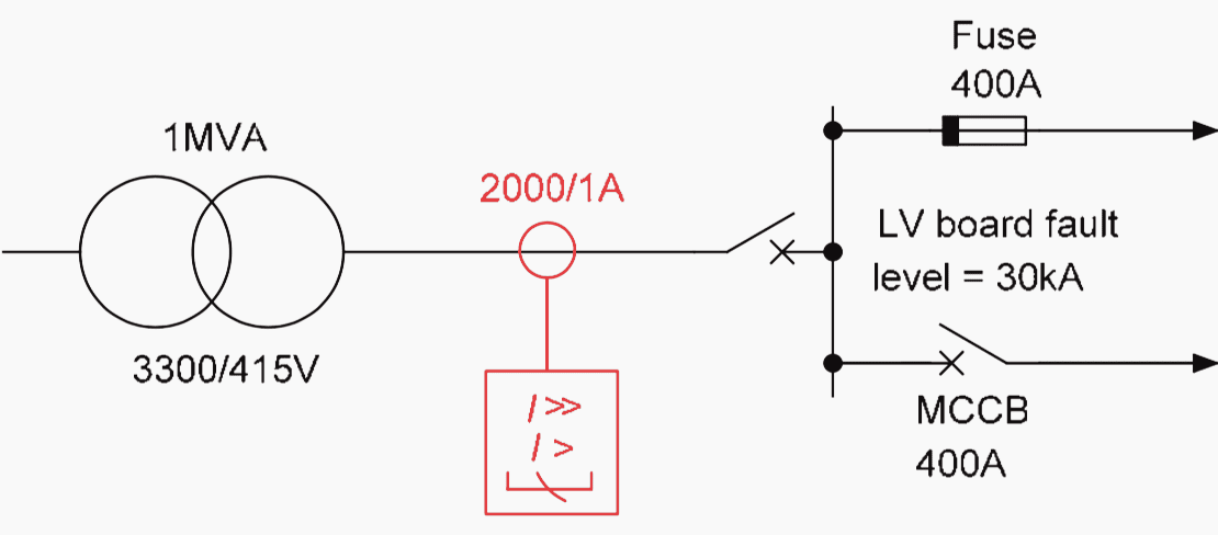
Discrimination is required between the relay and both the fuse and MCCB up to the 40kA fault rating of the board. To begin with, the time/current characteristics of both the 400A fuse and the MCCB are plotted in Figure 18.19.
2a. Determination of relay current setting
The relay current setting chosen must not be less than the full load current level and must have enough margin to allow the relay to reset with full load current flowing.
The latter may be determined from the transformer rating:
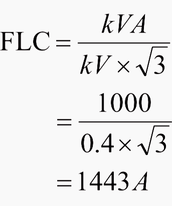
However, choice of a value at the lower end of this current setting range would move the relay characteristic towards that of the MCCB and discrimination may be lost at low fault currents.
It is therefore prudent to select initially a relay current setting of 100%.
2b. Relay characteristic and time multiplier selection
An EI characteristic is selected for the relay to ensure discrimination with the fuse.
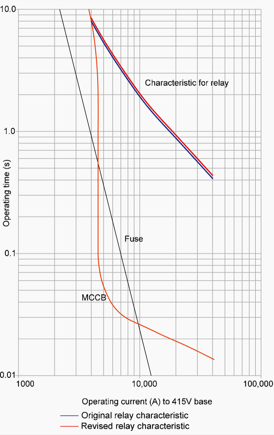
From Figure 4, it may be seen that at the fault level of 40kA the fuse will operate in less than 0.01s and the MCCB operates in approximately 0.014s. Using a fixed grading margin of 0.4s, the required relay operating time becomes 0.4 + 0.014 = 0.414s.
To obtain the required relay operating time of 0.414s:
TMS setting = 0.414 / 0.71 = 0.583
Use a TMS of 0.6, nearest available setting.
The use of a different form of inverse time characteristic makes it advisable to check discrimination at the lower current levels also at this stage. At a fault current of 4kA, the relay will operate in 8.1s, which does not give discrimination with the MCCB. A relay operation time of 8.3s is required.
To overcome this, the relay characteristic needs to be moved away from the MCCB characteristic, a change that may be achieved by using a TMS of 0.625. The revised relay characteristic is also shown in Figure 4.
3. Protection of a Dual-Fed Substation
As an example of how numerical protection relays can be used in an industrial system, consider the typical large industrial substation of Figure 5 below. Two 1.6MVA, 11/0.4kV transformers feeding a busbar whose bus-section CB is normally open.
The LV system is solidly earthed. The largest outgoing feeder is to a motor rated 160kW, 193kVA, and a starting current of 7 x FLC.
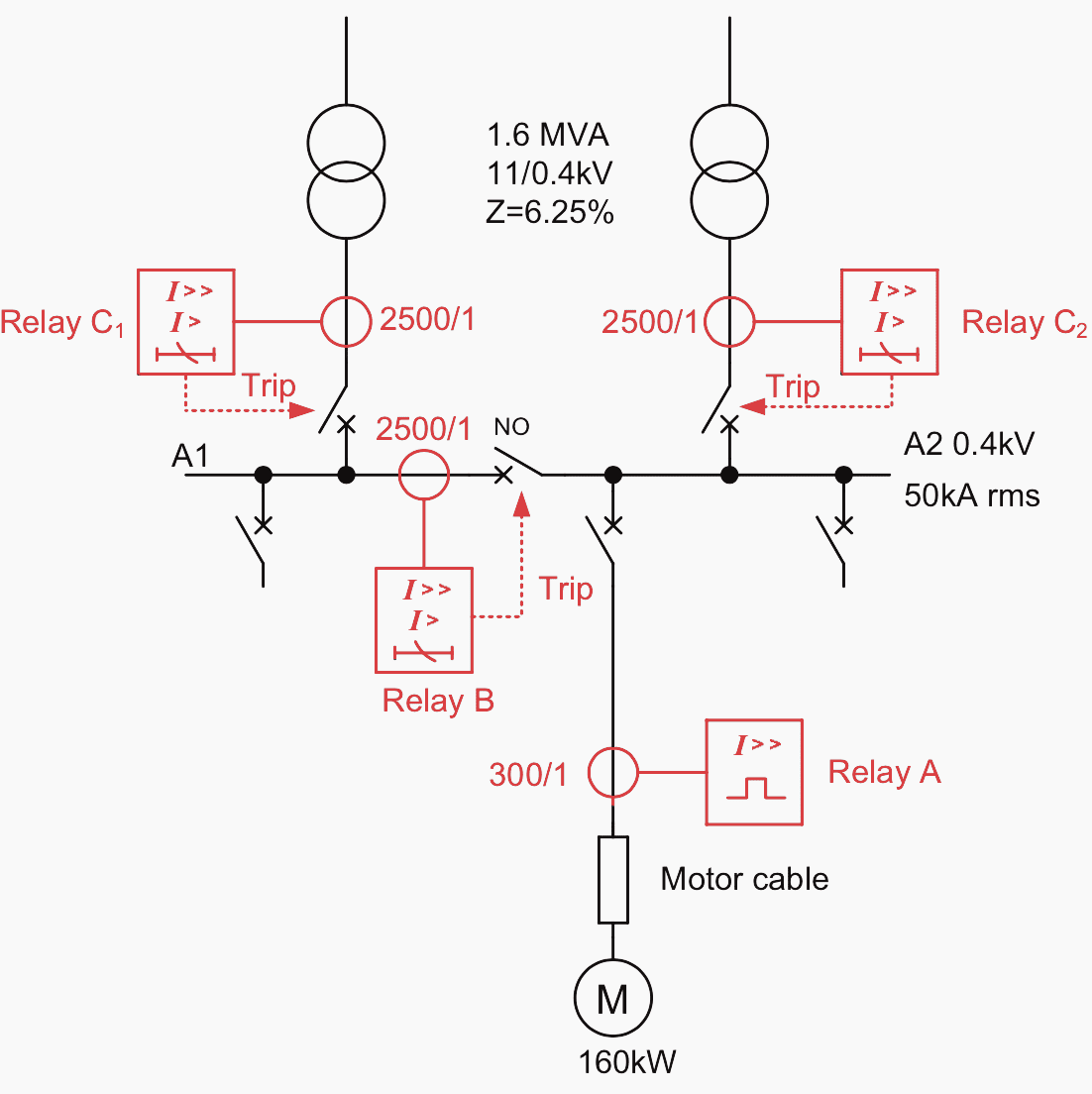
The transformer impedance is to IEC standards. The LV switchgear and busbars are fault rated at 50kA rms. To simplify the analysis, only the phase-fault LV protection is considered.
3a. General considerations
Analysis of many substations configured as in Figure 5 above shows that the maximum fault level and feeder load current is obtained with the bus-section circuit breaker closed and one of the infeeding CBs open. This applies so long as the switchboard has a significant amount of motor load.
The three-phase break fault level at the switchboard under these conditions is assumed to be 40kA rms.
Relays C1 and C2 are not required to have directional characteristics (read more about it below) as all three circuit breakers are only closed momentarily during transfer from a single infeeding transformer to two infeeding transformers configuration.
This transfer is normally an automated sequence, and the chance of a fault occurring during the short period (of the order of 1s) when all three CBs are closed is taken to be negligibly small. Similarly, although this configuration gives the largest fault level at the switchboard, it is not considered from either a switchboard fault rating or protection viewpoint.
It is assumed that modern numerical relays are used. For simplicity, a fixed grading margin of 0.3s is used.
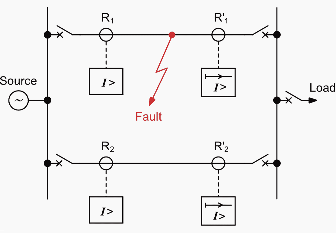
Application of Directional Relays
If non-unit, non-directional relays are applied to parallel feeders having a single generating source, any faults that might occur on any one line will, regardless of the relay settings used, isolate both lines and completely disconnect the power supply.
This is done by setting the directional relays R’1 and R’2 in Figure 6 with their directional elements looking into the protected line, and giving them lower time and current settings than relays R1 and R2.
The usual practice is to set relays R’1 and R’2 to 50% of the normal full load of the protected circuit and 0.1 TMS, but care must be taken to ensure that the continuous thermal rating of the relays of twice rated current is not exceeded.
3b. Motor protection relay settings
From the motor characteristics given, the overcurrent relay settings (Relay A) can be found using the following guidelines:
Thermal element- Current setting: 300A
- Time constant: 20 mins
- Current setting: 2.32kA
These are the only settings relevant to the upstream relays.
3c. Relay B settings
Relay B settings are derived from consideration of the loading and fault levels with the bus-section breaker between busbars A1 and A2 closed. No information is given about the load split between the two busbars, but it can be assumed in the absence of definitive information that each busbar is capable of supplying the total load of 1.6MVA.
With fixed tap transformers, the bus voltage may fall to 95% of nominal under these conditions, leading to a load current of 2430A.
The IDMT current setting must be greater than this, to avoid relay operation on normal load currents and (ideally) with aggregate starting/re-acceleration currents.
If the entire load on the busbar was motor load, an aggregate starting current in excess of 13kA would occur, but a current setting of this order would be excessively high and lead to grading problems further upstream.
It is unlikely that the entire load is motor load (though this does occur, especially where a supply voltage of 690V is chosen for motors – an increasingly common practice) or that all motors are started simultaneously (but simultaneous re-acceleration may well occur).
What is essential is that relay B does not issue a trip command under these circumstances – i.e. the relay current/time characteristic is in excess of the current/time characteristic of the worst-case starting/re-acceleration condition.
It is therefore assumed that 50% of the total bus load is motor load, with an average starting current of 600% of full load current (= 6930A), and that re-acceleration takes 3s.
A current setting of 3000A is therefore initially used.
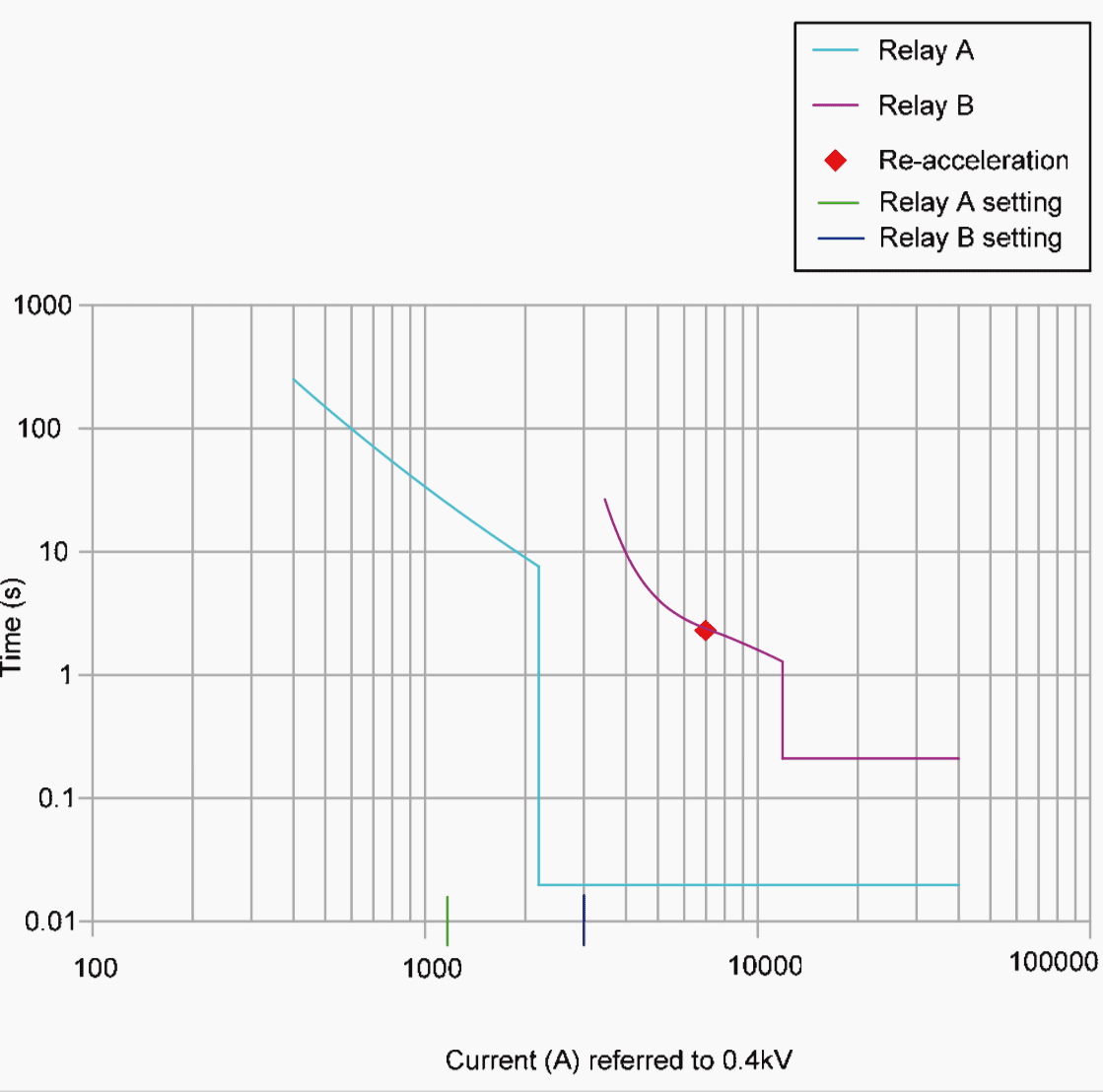
The SI characteristic is used for grading the relay, as co-ordination with fuses is not required. The TMS is required to be set to grade with the thermal protection of relay A under ‘cold’ conditions, as this gives the longest operation time of Relay A, and the re-acceleration conditions. A TMS value of 0.41 is found to provide satisfactory grading, being dictated by the motor starting/re-acceleration transient. Adjustment of both current and TMS settings may be required depending on the exact re-acceleration conditions.
Note that lower current and TMS settings could be used if motor starting/re-acceleration did not need to be considered.
The high-set setting needs to be above the full load current and motor starting/re-acceleration transient current, but less than the fault current by a suitable margin.
A setting of 12.5kA is initially selected. A time delay of 0.3s has to used to ensure grading with relay A at high fault current levels. Both relays A and B may see a current in excess of 25kA for faults on the cable side of the CB feeding the 160kW motor.
The relay curves are shown in Figure 6 below:
3d. Relays C settings
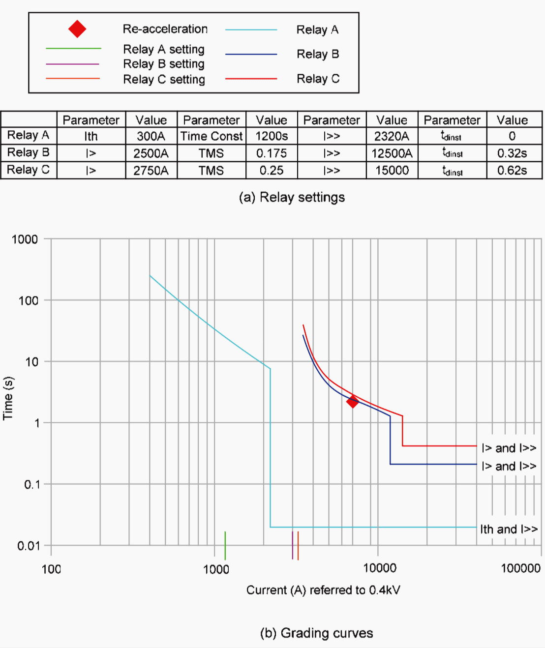
The setting of the IDMT element of relays C1 and C2 has to be suitable for protecting the busbar while grading with relay B. The limiting condition is grading with relay B, as this gives the longest operation time for relays C.
The current setting has to be above that for relay B to achieve full co-ordination, and a value of 3250A is suitable. The TMS setting using the SI characteristic is chosen to grade with that of relay B at a current of 12.5kA (relay B instantaneous setting), and is found to be 0.45.
The high-set element must grade with that of relay B, so a time delay of 0.62sec is required. The current setting must be higher than that of relay B, so use a value of 15kA.
The final relay grading curves and settings are shown in Figure 7.
3e. Comments on grading
While the above grading may appear satisfactory, the protection on the primary side of the transformer has not been considered.
IDMT protection at this point will have to grade with relays C and with the through-fault short-time withstand curves of the transformer and cabling. This may result in excessively long operation times. Even if the operation time at the 11kV level is satisfactory, there is probably a Utility infeed to consider, which will involve a further set of relays and another stage of time grading, and the fault clearance time at the Utility infeed will almost certainly be excessive.
This is achieved by setting relays C such that grading with relay B does not occur at all current levels, or omitting relay B from the protection scheme. The argument for this is that network operation policy is to ensure loss of supply to both sections of the switchboard does not occur for single contingencies.
As single infeed operation is not normal, a contingency (whether fault or maintenance) has already occurred, so that a further fault causing total loss of supply to the switchboard through tripping of one of relays B is a second contingency. Total loss of supply is therefore acceptable. The alternative is to accept a lack of discrimination at some point on the system.
Another solution is to employ partial differential protection to remove the need for Relay A, but this is seldom used. The strategy adopted will depend on the individual circumstances.
Reference // Network protection & automation guide by Alstom Grid
Related electrical guides & articles


Edvard Csanyi
Hi, I'm an electrical engineer, programmer and founder of EEP - Electrical Engineering Portal. I worked twelve years at Schneider Electric in the position of technical support for low- and medium-voltage projects and the design of busbar trunking systems.I'm highly specialized in the design of LV/MV switchgear and low-voltage, high-power busbar trunking (<6300A) in substations, commercial buildings and industry facilities. I'm also a professional in AutoCAD programming.
Profile: Edvard Csanyi

I really on this platform for most of solution
Thanks for the article, it’s Excellent
Thanks for the article,iwant to speak about fuse discrimination 100A fuse discriminate against 160A etc…
Your text does not match the diagrams. A 400A fuse needs at least a fuse above it of 640A rating, better 800A. It would be dangerous to leave the article in this state.
Edvard,
One further comment about fuse discrimination (or selectivity in American terminology): A manufacturer will typically state that a ratio of 1.6:1 is adequate to provide discrimination (e.g. a 100A fuse will discriminate against a 160A one), and will supply “I-squared t” figures that support this. But this assumes that both fuses are from the same manufacturer. In practice the designer can’t guarantee that a replacement fuse -even of the correct current rating- will come from the same firm. Therefore 2:1 would be a safer minimum ratio to ensure discrimination.
Edvard,
Thanks for the article. One glitch: In section 1 (fuse discrimination), Fig. 1a is actually a correct layout for proper discrimination but Fig. 1b would *not* discriminate (i.e with 500A and 400A fuses in series). This is in conflict with the wording, which describes scheme 1a as unsatisfactory & 1b as OK.
Regards, David.
très intéressant merci
Would you please tell me the corona inception and extinction voltage calculation and test procedure with and without corona ring and related table for those voltages in 63,132,230 and 400 kv power line.
Your kind attention and prompt reply will be appreciated.
Best regards : Reza Tousipanah