Search

Premium Membership ♕

Learn from experienced engineers and study specialized technical articles, studies & courses. Save 50% on courses with the Enterprise Plan.

Home / Technical Articles / Learn to read and understand single line diagrams and wiring diagrams

Introduction to SLDs

Single line diagrams are used in common engineering practice as graphical representation of electrical switchboard or assembly containing more sections, i.e. cubicles. Basically, they are simplified and digest picture of whole switchboard, showing only major power equipment and connections to other switchboards, usually with addition of major metering instruments which are used.

Learn to read and understand single line diagrams and wiring diagrams

Besides graphical symbols, most important data about equipment are shown as well. In the field of electrical diagrams, they are equivalent to contents or abstract in the field of written articles.

They are called “single line” because only one line is used to represent all three phases, and only one pole symbols are used to represent multipole switchgear or metering transformers placed in all lines.

Wiring diagrams are used to show control and signalization principle of operation inside switchboard. Usually they are given in form of electrical circuits between two lines which are representing control voltage potentials. Unlike single line diagrams, every drawn line matches one single wire which actually exists inside control part of the switchboard.

There are several widely used software packages intended for creation of electrical wiring diagrams.

The purpose of this article is to provide illustration and detailed explanation of both types of electrical diagrams mentioned, using a concrete example. Examples will be observed in critical manner, with some suggestions how to improve their competence and quality.


Example of single line diagram

In Figure 1 main low voltage distribution board consisted of five sections, i.e. cubicles, is shown in the form of single line diagram (SLD).

Nowadays, usually =FUNCTION +LOCATION -PRODUCT principle for creation of project tag for equipment is used, according to IEC 81346. Dashed rectangles are most often designation for so called location box, which may be a switchboard, control panel, substation or similar in example.

Example of single line diagram
Figure 1 – Example of single line diagram (click to expand)

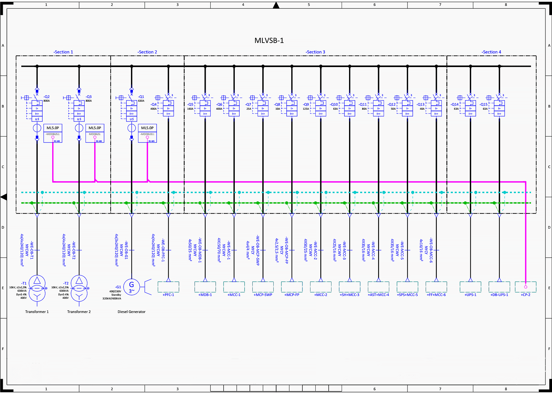
There are three incomings: transformer 1 (-T1), transformer 2 (-T2) and generator (-G1) and twelve outgoings, so fifteen circuit breakers in total are shown. “Standby” generator means that it will be started and used for supply only in case when grid supply isn’t available, i.e. in case when neither of two transformers is capable to provide power supply.

Note that standby rating of generator (in this case 320kW/400kVA) differs from some other, e.g. prime rating of same generator.

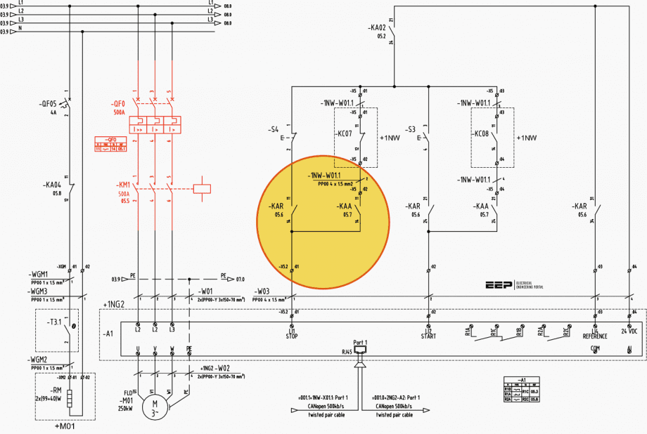
Black continuous line represents three live conductors or busbars (L1, L2, L3), blue dashed line stands for neutral (N), while green dash-dot line is protective earth (PE). This can be easily concluded, but it is better to be clearly marked in drawing.

Premium Membership Required

This technical article/guide requires a Premium Membership. You can choose an annually based Plus, Pro, or Enterprise membership plan. Subscribe and enjoy studying specialized technical articles, online video courses, electrical engineering guides, and papers. With EEP’s premium membership, you get additional essence that enhances your knowledge and experience in low- medium- and high-voltage engineering fields.

Check out each plan’s benefits and choose the membership plan that works best for you or your organization.

Log In »Purchase »

Premium Membership

Get access to premium HV/MV/LV technical articles, electrical engineering guides, research studies and much more! It helps you to shape up your technical skills in your everyday life as an electrical engineer.
More Information
author-pic

Miodrag Kokotovic

Graduated from Faculty of Electrical Engineering, within University of Belgrade, in the field of electrical power systems. Expert in electrical part of tender preparation, design, procurement, construction and commissioning of treatment plants and pumping stations, electrical power quality and energy management.

Leave a Comment

Tell us what you're thinking. We care about your opinion! Please keep in mind that comments are moderated and rel="nofollow" is in use. So, please do not use a spammy keyword or a domain as your name, or it will be deleted. Let's have a professional and meaningful conversation instead. Thanks for dropping by!

6  ×    =  sixty

Learn How to Design Power Systems

Learn to design LV/MV/HV power systems through professional video courses. Lifetime access. Enjoy learning!

Subscribe to Weekly Newsletter

Subscribe to our Weekly Digest newsletter and receive free updates on new technical articles, video courses and guides (PDF).
EEP Academy Courses - A hand crafted cutting-edge electrical engineering knowledge