
Estimated Study Time: 13 minutes
Detection of Faults
In general, as faults (short circuits) occur, currents increase in magnitude, and voltages go down. Besides these magnitude changes of the AC quantities, other changes may occur in one or more of the following parameters: phase angles of current and voltage phasors, harmonic components, active and reactive power, frequency of the power system, and so on.
 8 most essential relay operating principles in catching faults (on photo: Yandi Temporary Power Station Protection Relay Test; credit: aptuspower.com.au)
Relay operating principles may be based upon detecting these changes, and identifying the changes with the possibility that a fault may exist inside its assigned zone of protection.
We will divide relay operating principles into categories based upon which of these input quantities a particular relay responds.
- Level Detection
- Magnitude Comparison
- Differential Comparison
- Phase Angle Comparison
- Distance Measurement
- Pilot Relaying
- Harmonic Content
- Frequency Sensing
1. Level Detection
This is the simplest of all relay operating principles. As indicated above, fault current magnitudes are almost always greater than the normal load currents that exist in a power system. Consider the motor connected to a 4 kV power system as shown in Figure 1.

The full-load current for the motor is 245 A. Allowing for an emergency overload capability of 25%, a current of 1.25 × 245 = 306 A or lower should correspond to normal operation. Any current above a set level (chosen to be above 306 A by a safety margin in the present example) may be taken to mean that a fault, or some other abnormal condition, exists inside the zone of protection of the motor.
The level above which the relay operates is known as the pickup setting of the relay. For all currents above the pickup, the relay operates, and for currents smaller than the pickup value, the relay takes no action. It is of course possible to arrange the relay to operate for values smaller than the pickup value, and take no action for values above the pickup.
An undervoltage relay is an example of such a relay.
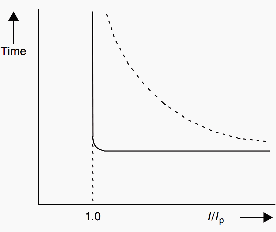
The operating characteristics of an overcurrent relay can be presented as a plot of the operating time of the relay versus the current in the relay. It is best to normalize the current as a ratio of the actual current to the pickup setting.
The operating time for (normalized) currents less than 1.0 is infinite, while for values greater than 1.0 the relay operates. The actual time for operation will depend upon the design of the relay. The ideal level detector relay would have a characteristic as shown by the solid line in Figure 2.
In practice, the relay characteristic has a less abrupt transition, as shown by the dotted line.
2. Magnitude Comparison
This operating principle is based upon the comparison of one or more operating quantities with each other. For example, a current balance relay may compare the current in one circuit with the current in another circuit, which should have equal or proportional magnitudes under normal operating conditions.
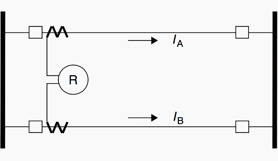
The relay will operate when the current division in the two circuits varies by a given tolerance. Figure 3 shows two identical parallel lines that are connected to the same bus at either end.
Similar logic would be used to trip line B if its current exceeds that in line A, when the latter is not open. Another instance in which this relay can be used is when the windings of a machine have two identical parallel sub-windings per phase.
3. Differential Comparison
Differential comparison is one of the most sensitive and effective methods of providing protection against faults. The concept of differential comparison is quite simple, and can be best understood by referring to the generator winding shown in Figure 4.
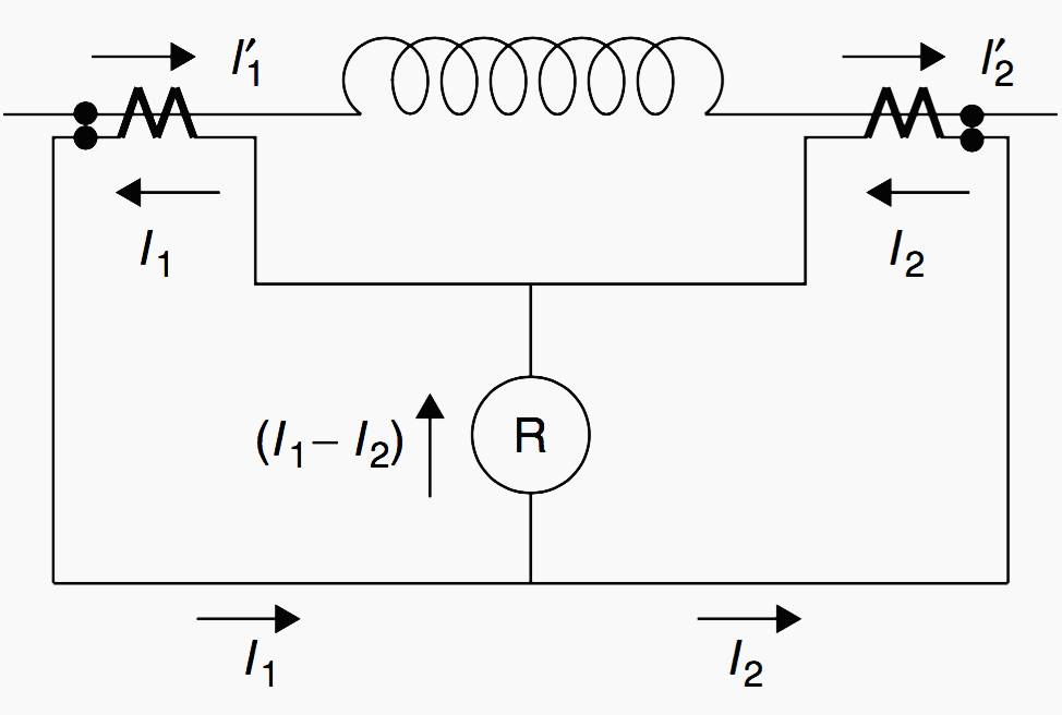
As the winding is electrically continuous, current entering one end I1, must equal the current leaving the other end I2. One could use a magnitude comparison relay described above to test for a fault on the protected winding.
In either case, the protection is termed a differential protection. In general, the differential protection principle is capable of detecting very small magnitudes of fault currents. Its only drawback is that it requires currents from the extremities of a zone of protection, which restricts its application to power apparatus, such as transformers, generators, motors, buses, capacitors, and reactors.
4. Phase Angle Comparison
This type of relay compares the relative phase angle between two AC quantities. Phase angle comparison is commonly used to determine the direction of a current with respect to a reference quantity.
For instance, the normal power flow in a given direction will result in the phase angle between the voltage and the current varying around its power factor angle, say approximately ±30°. When the power flows in the opposite direction, this angle will become (180° ± 30°).
Similarly, for a fault in the forward or reverse direction, the phase angle of the current with respect to the voltage will be −φ and (180◦ − φ), respectively, where φ, the impedance angle of the fault circuit, is close to 90° for power transmission networks.
These relationships are explained for two transmission lines in Figure 5.

This difference in phase relationships created by a fault is exploited by making relays that respond to phase angle differences between two input quantities – such as the fault voltage and the fault current in the present example.
5. Distance Measurement
As discussed above, the most positive and reliable type of protection compares the current entering the circuit with the current leaving it. On transmission lines and feeders, the length, voltage, and configuration of the line may make this principle uneconomical.
Instead of comparing the local line current with the far-end line current, the relay compares the local current with the local voltage. This, in effect, is a measurement of the impedance of the line as seen from the relay terminal.
An impedance relay relies on the fact that the length of the line (i.e., its distance) for a given conductor diameter and spacing determines its impedance.
6. Pilot Relaying
Certain relaying principles are based upon the information obtained by the relay from a remote location. The information is usually – although not always – in the form of contact status (open or closed). The information is sent over a communication channel using power line carrier, microwave, or telephone circuits.
7. Harmonic Content
Currents and voltages in a power system usually have a sinusoidal waveform of the fundamental power system frequency. There are, however, deviations from a pure sinusoid, such as the third harmonic voltages and currents produced by the generators that are present during normal system operation.
Other harmonics occur during abnormal system conditions, such as the odd harmonics associated with transformer saturation, or transient components caused by the energization of transformers.
8. Frequency Sensing
Normal power system operation is at 50 or 60 Hz, depending upon the country. Any deviation from these values indicates that a problem exists or is imminent. Frequency can be measured by filter circuits, by counting zero crossings of waveforms in a unit of time, or by special sampling and digital computer techniques.
Frequency-sensing relays may be used to take corrective actions that will bring the system frequency back to normal.
Relays may be constructed from electromechanical elements such as solenoids, hinged armatures, induction discs, solid-state elements such as diodes, silicon-controlled rectifiers (SCRs), transistors or magnetic or operational amplifiers, or digital computers using analog-to-digital converters and microprocessors.
It will be seen that, because the electromechanical relays were developed early on in the development of protection systems, the description of all relay characteristics is often in terms of electromechanical relays. The construction of a relay does not inherently change the protection concept, although there are advantages and disadvantages associated with each type.
Reference // Power System Relaying by Stanley H. Horowitz – Retired Consulting Engineer American Electric Power) and Arun G. Phadke – University Distinguished Research Professor (Purchase hardcopy from Amazon)
Related electrical guides & articles


Edvard Csanyi
Hi, I'm an electrical engineer, programmer and founder of EEP - Electrical Engineering Portal. I worked twelve years at Schneider Electric in the position of technical support for low- and medium-voltage projects and the design of busbar trunking systems.I'm highly specialized in the design of LV/MV switchgear and low-voltage, high-power busbar trunking (<6300A) in substations, commercial buildings and industry facilities. I'm also a professional in AutoCAD programming.
Profile: Edvard Csanyi

i think your ducoment is very well