
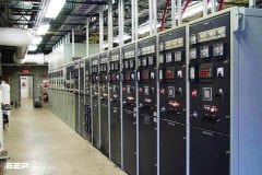
Secondary Distribution
A high level of interconnection, either ring or mesh, to ensure a high degree of availability of supply to the consumer, characterises secondary distribution networks in urban areas. Domestic, industrial and commercial consumers will suffer great inconvenience through only a relatively short loss in supply of only a few hours, with business likely to suffer considerable financial loss if an interruption is longer than 2-4 hours.
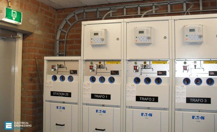 Secondary Distribution Networks In Urban Areas (on photo: EATON's MV RMU 'Xiria'; credit: bemtech.nl)
For domestic consumers, loss of supply for between 4-8 hours is largely an inconvenience, though loss may result from spoilage of freezer contents, etc. and in cold weather may place vulnerable sections of the community at risk.
Such hazards for a privatised Utility give rise to the potential for significant financial loss, through claims for compensation.
Ring Main Unit (RMU)
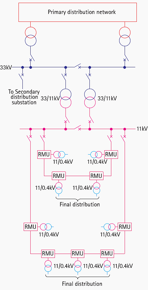
A typical urban secondary distribution system is shown in Figure 1. There is a large proportion of underground cable, and final feeders to LV distribution substations take the form of feeders from Ring Main Units (RMU’s).
Several RMU’s are connected in a loop fed from one or more substations, the loop normally being open at some point. The open point is normally chosen to equalise loading at both ends of the ring as far as possible.
The cables forming the ring and all associated switchgear, etc., are sized for single-end feeding of the whole ring, to allow for an outage affecting the ring between a substation and the first RMU, or at the substation itself.
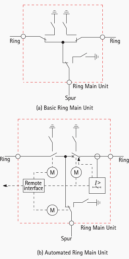
The arrangement of an individual RMU is shown in Figure 2(a). For many years, only local operation and indications (trip/healthy) were provided, so that switching operations required a visit from field staff. Trips at an RMU resulting in loss of supply to consumers were annunciated through customer complaints, no direct indication to the control room was provided.
The individual items of plant have developed over many years and are generally reliable, taken individually. Major failures of a complete secondary distribution system are rare, and usually stem from inadequate specification of the original equipment, or failure to monitor the condition of equipment with time.
This is especially the case where loading and/or environmental conditions have changed.
In the centre of a large city, excavation is not popular and will be expensive. Traffic congestion will ensure that the response time for a repair crew to arrive at a substation after a fault has been reported is not trivial, especially where (in some privatised Utilities), penalties may be imposed for loss of supply to consumers lasting more than 60 minutes.
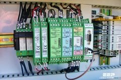
Advantages of automation techniques
The application of automation techniques has therefore many advantages. This will usually require the provision of extra features to an RMU. The most common features added are:
- Capability for remote operation – addition of actuators for open/close operation of the various devices that are capable of being operated from a remote location
- Provision of remote indications of status of the various devices
- Addition of Fault Passage Indicators (FPI’s). An FPI is a sensor that detects passage of current in excess of a defined value, and therefore provides an indication that the fault is further from the supply point (for a radial-fed system) than the FPI
- Addition of a protection relay for phase/earth faults
Note that once it has been decided to provide remote control or indication, some form of communications interface is also required and the incremental cost of providing both remote control and indication instead of one or the other is very small.
Automated RMU //
A typical configuration for an RMU with all options fitted is shown in Figure 2(b). Traditional manual operation of RMU’s can be replaced by remote control. Many existing designs of RMU can be adapted in this way, while all new designs have this feature as standard.
The remote communications feature provides the following features:
- Issuing of commands to open/close the circuit breaker, etc.
- Provision of status information (position, availability) etc.
- Voltage and current data
Provision of remote indication of status to a Control Centre enables the response time to a fault to be reduced. The reduction in customer complaints and compensation paid can be justification in itself.
Equipment that is used rarely may fail to operate when called upon to do so. Much effort has been paid in protection relay design to avoid this problem, and digital and numerical relays generally have a self-checking function that runs regularly and is arranged to alarm if the function detects an internal fault.
However, circuit breakers and other switching devices that may not operate for a considerable period can get stuck in their normal position and thus fail to operate when commanded to. A number of major system collapses have been known to occur because of such problems, it being not always possible to provide backup protection that will operate in sufficient time.
One solution to this problem is to exercise such equipment on a regular basis. This can be done at little cost to the Utility if carried out remotely, but is prohibitively expensive if carried out on a local manual basis.
Finally, through an improved knowledge of network performance, network enhancements may be able to be postponed or eliminated, which is a substantial bonus as the costs of installing new cables in urban areas can be very high.
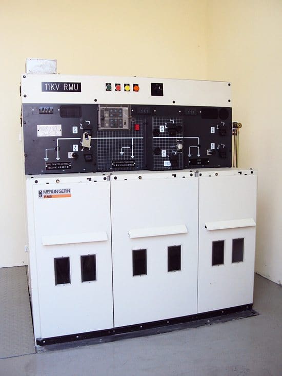
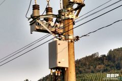
Figure 3 shows a modern RMU suitable for installation indoors – practice varies between countries in such matters, with outdoor installation also being common.
Reference // Network Protection and Automation Guide – Areva


Hai sir, I never seen a protection relay in rmu. There is hrc fuse for transformer protection, how the cable will be protected? I hav seen pilot wire protection in ring main substations. If there is 5 rmus with 1600kva 10 transformers how to size the 11kv cable. Thanks