
Estimated Study Time: 8 minutes
Well, yes and no…
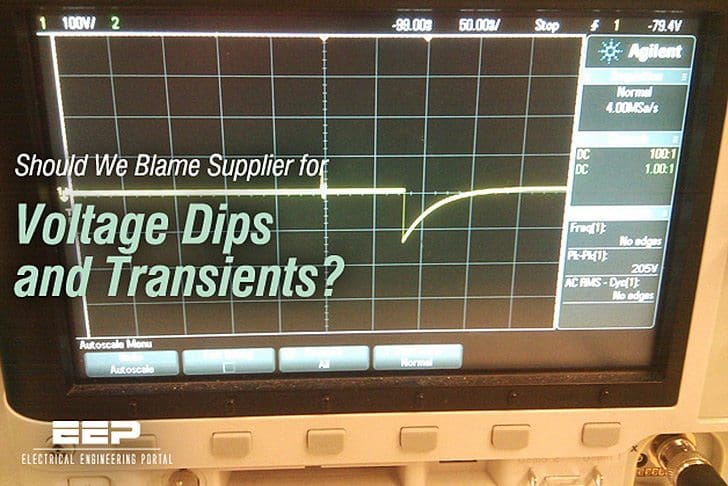
Voltage dips and transients are usually blamed on the supplier, but this is often unfair. There are many potential on-site causes; for example, starting of heavy loads may cause voltage dips and switching of inductive loads will generate transients.
Let’s talk about how actually voltage dips and transients are created and how they influence the power network:
Voltage dips
Heavy loads, such as large motors, draw very high starting currents for several seconds as the rotor accelerates causing a voltage drop in the wiring feeding it. This voltage drop will be much greater if the wiring has not been carefully rated to account for the magnitude of the starting current.
If other equipment is fed from the same feeder, it will be subject to the same voltage drop, and may fail as a result.

Good installation practice is the key to reducing this problem; large loads should have dedicated feeders of adequate cross-section right back to the point of common coupling (PCC) so that the heavy load is separated from other, more sensitive, loads. Maintenance procedures should ensure that this circuit separation is not destroyed during system extension.
Modern low power electronic equipment is often specified as operating over a very wide supply voltage range – indeed many units are claimed to operate over the 100V to 250V range without adjustment. This can be misleading – Most equipment uses a switched mode power supply (SMPS) unit that draws pulses of current from the supply, once per half cycle, to charge an internal capacitor. Load power is drawn via a regulator, discharging the capacitor that is recharged by the next supply pulse.
However, since the energy stored in the capacitor is proportional to the square of the supply voltage, a 10% reduction in supply voltage results in a nearly 20% drop in stored energy. Lower cost units have more limited hold-up times and may fail to supply the required load during a voltage dip.
In particular, wide supply voltage range units may have very low hold-up times at the lower end of the input range. It is important to remember that many computer peripherals, such as printers and communications modems, use this type of supply.
Where the electricity supply is the source of voltage dips it will be necessary to provide voltage regulation, either for the whole site or for selected sensitive equipment.

Ferroresonant transformers (figure above), sometimes called constant voltage transformers, operate with a saturated core and resonant circuit to maintain the output voltage as the input voltage varies, the primary current varying to compensate. The device operates satisfactorily over a narrow range of output loadings.
The modern equivalent uses a multi-tapped transformer and a solid state tap changer and is fast, accurate and maintenance free. The transformer may be an autotransformer, but in this case noise isolation is poor and dual-wound shielded transformers are preferred.
It is important that the control circuitry for such devices is true RMS sensing, otherwise distortion on the supply will be mis-interpreted as a change in voltage.
Transients
Transients are most frequently caused by switching of inductive or capacitive loads. Wherever possible, suppression should be applied at the source to prevent the transient propagating and coupling to other circuits. When the source of the transient is off-site, the suppression techniques outlined below should be used.

Low magnitude transients are unlikely to result in damage but will cause noise and can be reduced by the provision of line filters or isolating transformers. Typical small equipment line filters (6 Amp rating) have attenuation figures of 22dB for differential and 8dB for common mode noise at 150 kHz, rising to a maximum of 70dB at 30 MHz.
Isolation transformers provide good noise isolation providing that adequate electrostatic shielding is provided between the windings. Single, double and triple shielded types are available with increasing levels of noise attenuation.

Transients can reach several thousand volts and can seriously damage equipment but, fortunately, protection is achieved easily and economically by the use of transient voltage surge suppressers.
Typically metal oxide varistors (MOV) are used; these devices have very high resistance at normal voltage but above their breakdown voltage the resistance becomes very low, so clamping the transient to the breakdown voltage of the device. The clamp effect requires the
voltage of the transient to be dropped in the impedance of the supply so a high transient current must flow and this often results in noise coupling to adjacent wiring, including signal and network cabling. For this reason, it is better to fit suppressers near the source of the problem rather than at every other device that may be affected.
It will often be found necessary to follow the suppressor with a filter to further attenuate the transient. MOVs can pass very large currents of short duration but, because their power handling capability is quite low, they are not suitable for clamping repetitive spikes.
Reference // Electrical Design – A Good Practice Guide – Copper Development Association
Related electrical guides & articles


Edvard Csanyi
Hi, I'm an electrical engineer, programmer and founder of EEP - Electrical Engineering Portal. I worked twelve years at Schneider Electric in the position of technical support for low- and medium-voltage projects and the design of busbar trunking systems.I'm highly specialized in the design of LV/MV switchgear and low-voltage, high-power busbar trunking (<6300A) in substations, commercial buildings and industry facilities. I'm also a professional in AutoCAD programming.
Profile: Edvard Csanyi

Working as a Machineries Maintenance Engineer. At Const site we have various type of hoisting applications for which VFD driven motors are used.
Apart from this various types of motor driven equipment are available which account for inductive loads.
What protections can be employed to protect the VFD ??