Nearly 100 years ago, electrode gaps (rod, sphere, or pipe) were used to limit overvoltages on equipment (Sakshaug, 1991). Some of these systems, particularly pipe gaps, may still be in service today. However, the characteristic of gap sparkover voltage vs. surge front time does not match up well with the strength vs. front characteristics of most insulation; that is, it is difficult to coordinate.
The next evolutionary step was to add a resistive element in series with the gap, in order to limit the power follow current after an arrester discharge operation. The current limiting would hopefully allow the arrester to clear this power follow current, instead of relying on a nearby breaker or fuse. At the same time, the resistor voltage during a discharge must be low enough that it does not allow an excessive voltage to appear on the protected equipment.
These competing requirements led to the use of expensive and complicated nonlinear resistive elements, some involving both solid and liquid materials with high maintenance burdens.
Beginning around 1930, silicon carbide (SiC) was used for the nonlinear resistive elements, leading to much better protective characteristics. Because the SiC would conduct significant current at nominal voltage, it was necessary to provide a sparkover gap that prevents conduction at nominal voltage. After an arrester discharge, these gaps must reseal against the power follow current, otherwise, the arrester would fail thermally. In the mid 1950s, active gaps were developed for SiC arresters.
These active gaps contain auxiliary elements that would:
- Pre-ionize the sparkover gap to obtain better surge protective levels and
- Elongate the power follow arc, and move its attachment points, to obtain better interruption performance.
SiC arresters were successfully applied on transmission systems up to 345 kV, but some limitations appeared with regard to switching surge protection, energy discharge capability, and pressure relief capability.
Having both gaps and SiC blocks, the arrester height increased to the point where it was difficult to vent the pressure built-up during a fault, which limited the arrester’s pressure relief rating.
Due to their discharge characteristics vs. frequency or front time, the SiC surge arresters were optimized for lightning. They were less effective for steeper-fronted surges and slow-fronted switching surges.
In the mid 1970s, metal oxide surge arresters were developed into commercial products (Sakshaug, et al., 1977). The metal oxide blocks are much more nonlinear than silicon carbide, so that they conduct only a few milliamperes at nominal AC voltage. It eventually became possible to dispense with gaps completely, although earlier designs made some use of gaps (see Fig. 1).

Metal oxide surge arresters have several major advantages over the earlier silicon carbide arresters:
- Active gaps are not necessary, leading to improved reliability
- Metal oxide can discharge much more energy per unit volume than silicon carbide
- Metal oxide provides better protection across the range of surge wavefronts than silicon carbide, and in fact, protects effectively against switching surges
- The decrease in arrester height, caused by eliminating sparkover gaps, leads to higher pressure relief ratings
Virtually all new applications will use metal oxide surge arresters. Metal oxide has enabled some new applications, like series capacitor protection and overhead line switching surge control that were not possible with silicon carbide.
However, many silicon carbide arresters are still in service. Some investigators have noted high silicon carbide arrester failure rates, due to moisture ingress, after several years of service on medium-voltage distribution systems. This experience does not necessarily apply to surge arresters in substations. If such problems arise, it would make sense to systematically replace silicon carbide arresters on a system. Otherwise, assuming that the original application was proper, the older silicon carbide arresters could remain in service.
Figure 1 shows the general use of gaps in surge arresters. The gapped design (1a) applies to silicon carbide, whereas the gapless design (1d) applies to the latest generation of metal oxide. One manufacturer used the shunt gap (1b) in early metal oxide arresters. At steady state, both nonlinear elements would support the nominal voltage, somewhat reducing the current. During a surge discharge, the shunt gap would sparkover to bypass the smaller section of metal oxide, thereby reducing the discharge voltage and providing somewhat better protection. Another manufacturer used the series gap with capacitive grading (1c) in early metal oxide arresters. At steady state, this decreases the voltage on the metal oxide.
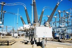
During a surge discharge, the gap sparks over ‘‘immediately’’ due to the capacitive grading. The latest generations of metal oxide do not need these gaps, although there is some consideration for using gaps to achieve specific goals (e.g., coordinating arresters, withstanding temporary overvoltages). The surge arrester must be installed on something, such as a transformer tank or a pedestal. It must also be connected to the protected system, typically through a wire or lead. Later, it will be shown that these connections have important effects on the overall protection, especially for steep surges.
The pedestal and lead, both length and location, must be considered as part of the overall arrester installation. On distribution systems, a ground lead disconnector is often used with the surge arrester. If the arrester fails and then conducts current on a steady-state basis, the disconnector will detonate and disconnect the base of the arrester from ground. This should happen in approximately 1 sec, or faster.
The arrester may then remain connected to the system until maintenance personnel have a chance to replace it. No breaker or fuse need operate to isolate the failed arrester; if the arrester is the only thing that failed, no customers need to lose their electric service. Of course, the arrester is not providing any surge protection during this period with its ground lead disconnected. There would be a clear visual indication that the ground lead has been disconnected; it will be ‘‘hanging down’’ below the arrester. Regular visual inspections are necessary to maintain surge protection whenever ground-lead disconnectors are used.
Many surge arresters in substations or industrial facilities have been installed with ‘‘surge counters.’’
These are accessories to be installed in the surge arrester’s ground-lead connection. Two functions may be provided:
- A steady-state current meter, calibrated in mA. If this current increases over time, it may indicate thermal damage to the surge arrester. However, the presence of harmonics or external leakage currents would complicate the assessment.
- A counter indicates the number of surge current discharges above a certain threshold, which may depend on frequency or front time. Even if the count is accurate, it does not mean that the discharge voltage reached any particular level during those events.
To use surge counters effectively, it is important to track the readings on a regular basis, beginning at the time of commissioning.
SOURCE: Surge Arresters – Thomas E. McDermott