
Estimated Study Time: 11 minutes
Choosing The Earthing Point
Normally in directly earthed and effectively earthed systems, every available neutral point is earthed. Deviations from this occur when the transformer’s neutral points are left unearthed. This is done to limit the maximum earth fault current which can arise to reasonable values. In these cases, the neutral point is equipped with surge arresters.
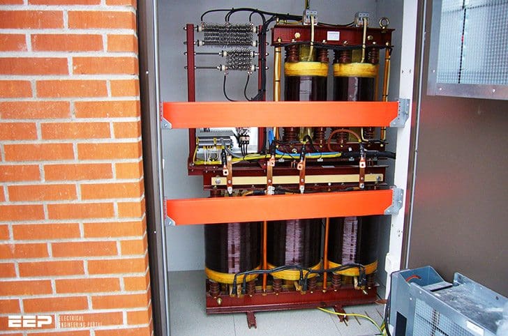 How To Choose System's Earthing Point And What's The Practice Throughout The World (on photo: Neutral Earthing Resistor; credit: swedishneutral.se)
This is only acceptable if the network at all operation modes still can be considered as effectively earthed (X0≤3X1). The other earthing methods it is somewhat more complicated.
For example, the wish to keep the earth fault current more or less constant, at the same time as the network always must be earthed independently of the operation mode, gives contradictions and difficult choices.
1. Individual earthing in every neutral point of the power sources
When there only are a few generators or transformers in a station, individual neutral-point impedances are often used. Hereby the neutral-point connection is fixed without intervening connection devices.
When just two power sources are used individual neutral-point impedances are referred to a common earthing impedance.
When several power sources are used the earth fault current is increased every time a power source is connected and can reach unwanted values. At resistance earthing every resistor must be dimensioned for a current high enough to satisfy the operation of the relay equipment, when this is working alone.
Consequently, the total earth fault current at several aggregates becomes several times the value required for a satisfying relay function. A disconnector is thus often provided to enable disconnection of resistors when the system is in parallel service condition.
Together with generators or motors, multiple earthing can be unsuitable due to the danger of circulating third harmonic currents.
2. Common earthing through a neutral busbar
When there are more than two generators or transformers, in a station it can be preferable to use just one neutral-point apparatus. The neutral point of every power source is then connected through a coupling device, breaker or disconnector, to a common neutral busbar which is earthed through a resistor or a reactor.
This arrangement keeps the earth fault current at optimal size since it never has to be higher than what is needed to avoid overvoltages or to give a safe relay protection operation. There is always the same earth fault current independent of the service condition.
Two different connections with neutral-point busbars are shown in figures 2 and 3.
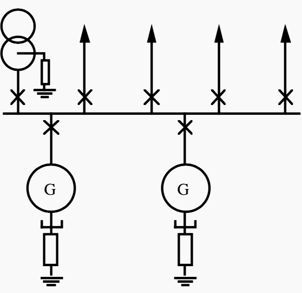
Connection #1
Resistance earthing, of the generator neutral-point, with a neutral busbar and individual neutral-point breakers.
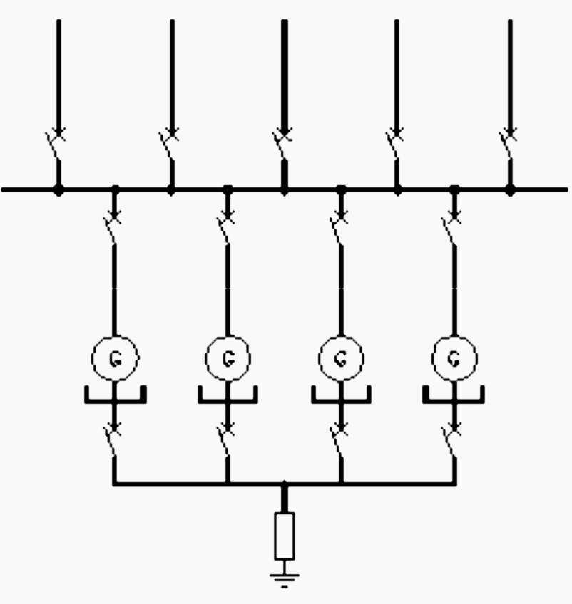
Connection #2
Resonance earthing, of transformer neutral-point, with a neutral busbar and individual disconnectors.
Due to the third harmonic problem only one of the breakers in figure 2 resp. 3 should be closed at a time. When one of the generators is taken out of service it’s important that the corresponding neutral point breaker (or disconnector) is opened.
This since the neutral busbar will be current carrying at an earth fault and achieve the phase voltage to earth.
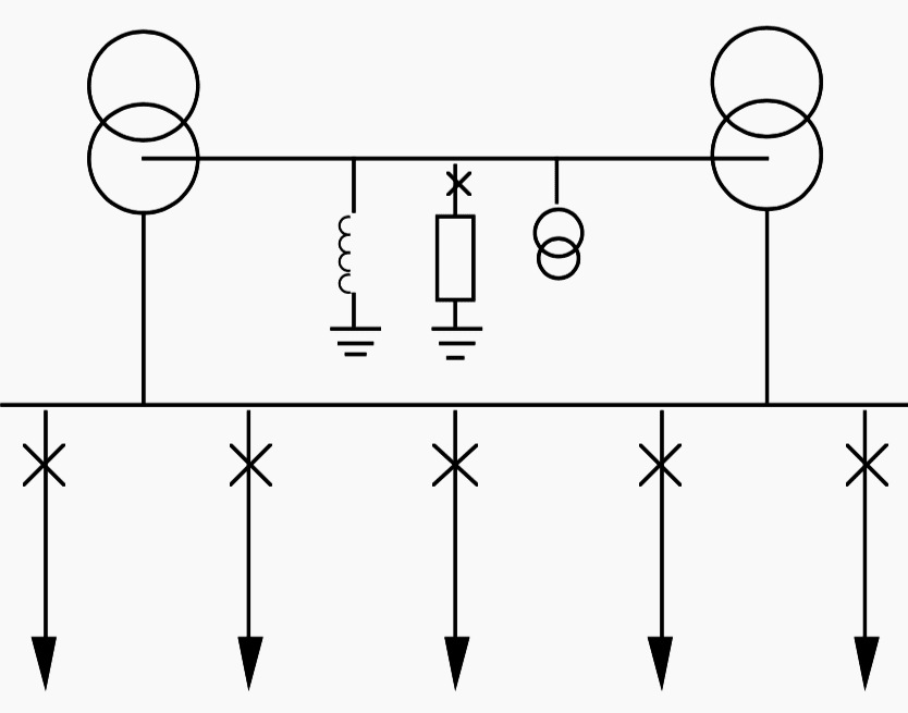
3. Common earthing through an earthing transformer on the busbar
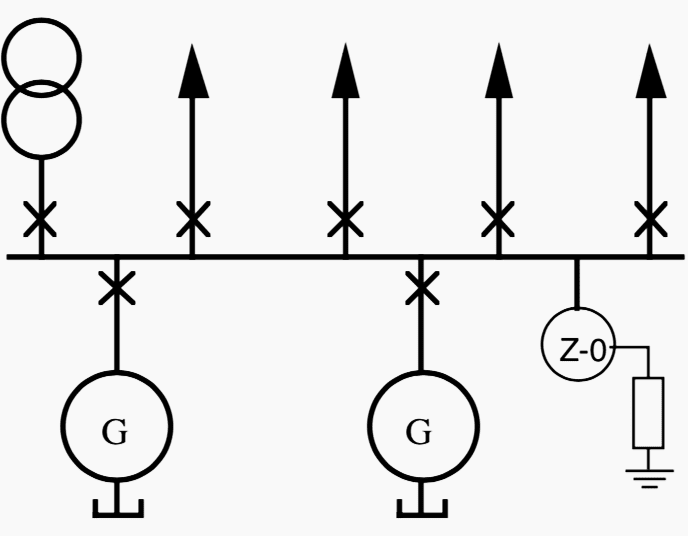
An effective and often cheap way to make sure that the system always is correctly earthed is to connect any earthing transformer to the busbar. See Figure 4 which shows the same network as in Figure 1 but with an alternative method of earthing.
Practice Of Earthing
The practice of earthing differs very much from country to country. It is however possible to distinguish countries as Germany, Netherlands, and Sweden etc., where the main direction has been to protect the telephone networks and people.
A summation of the practices in different countries would, unfortunately, be very extensive, especially as the networks differ even within the countries.
However, a simplified summary follows below.
- Voltages over 100 kV
- Voltages between 25 and 100 kV
- Voltages between 1 and 25 kV for distribution with or without direct connected generators
- Generator network
- Voltages under 1 kV
1. Voltages over 100 kV
At high voltages there is an economic advantage in earthing the network directly (effectively). By doing so transformers and insulators etc. can be built with a lower test voltage at neutral and a graded insulation, which gives considerable cost savings.
In most countries it’s normal with a direct earthing at voltages over 100 kV. In e. g. Germany, Netherlands and Norway, however there are 130kV networks with resonance earthing.
2. Voltages between 25 and 100 kV
- USA – Most parts of the country are directly earthed but resistance and reactance earthing occur.
- United Kingdom – Most parts of the country are resistance earthed in the neutral-point of the power source. The resistance gives an earth fault current of the same size as the rated current in the trans- former. Some 33 kV networks can however be resonance earthed.
- Germany, Switzerland, Austria, Netherlands, Belgium, Spain, Ireland, Norway, Denmark, Sweden and Japan – Use resonance earthing.
- France and South Africa – Most parts of the countries are resistance earthed (reactance earthing occur). France is investigating the possibilities of a change over into resonance earthing (with transient measuring earth fault protection).
- Australia – Uses direct earthing and resonance earthing. Some 33 kV networks can however be resistance earthed.
- New Zealand – Uses direct earthing
- India and Malaysia – Resonance earthing is the most common earth- ing but also resistance earthing occurs. And in India also direct earthing can occur.
3. Voltages between 1 and 25kV for distribution with or without direct connected generators
In most countries varying types of earthing can occur but the resonance earthing is the most common. However unearthed net- work as well as high resistance earthings can occur.
Resistance earthing is most common in USA and England. Direct earthing is most common in Australia and Canada but can also occur in USA and Finland.
4. Generator network
Generator networks, are the type of limited networks that consist of one or several generators connected to a primary transformer, but without direct connection to the distribution lines.
These limited networks are almost always high resistance earthed. However at new constructions unearthed networks rarely occurs.
5. Voltages under 1kV
These networks are normally direct earthed. In industries with pure motor networks, unearthed or high resistance earthed networks are mainly used.
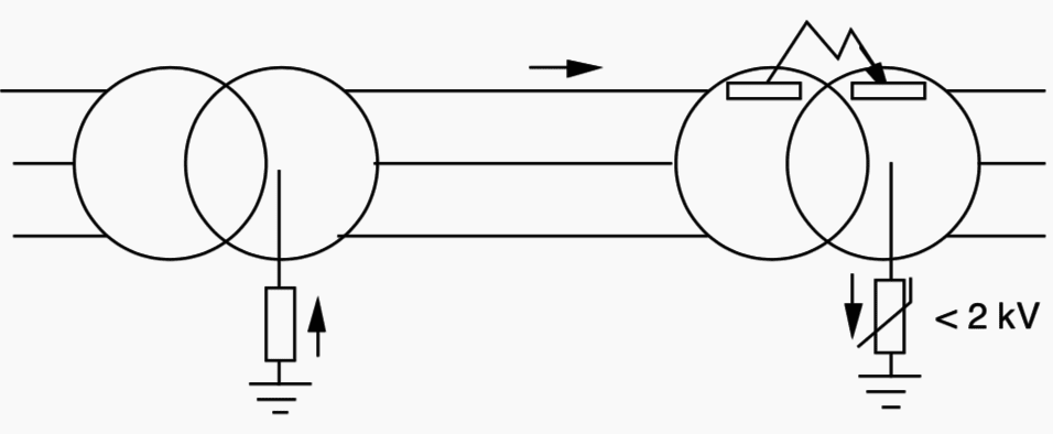
At flash-over from the network, at the primary side of the transformer (normally a high resistance earthed 10 kV network) the resistance in the resistor will be so low that the overvoltage in the low voltage network will be limited to 2 kV.
See figure 5 below.
Reference // Protection Application Handbook – BA THS / BU Transmission Systems and Substations by ABB
Related electrical guides & articles


Edvard Csanyi
Hi, I'm an electrical engineer, programmer and founder of EEP - Electrical Engineering Portal. I worked twelve years at Schneider Electric in the position of technical support for low- and medium-voltage projects and the design of busbar trunking systems.I'm highly specialized in the design of LV/MV switchgear and low-voltage, high-power busbar trunking (<6300A) in substations, commercial buildings and industry facilities. I'm also a professional in AutoCAD programming.
Profile: Edvard Csanyi

CAPCUÑAR SSTEMAS A TIERRA.MANTENIMIENTO Y ENSAMBLE DE SUBESTACIONES
Thank you for that interesting and knowledge post, they are contributing a lot to my understanding of the electrical world
Thank you for the knowledgeable information.
Regarding Earthing system, I wish to know the following:
1. Do you recommend to interconnect the 11kV and LV Earthing together in the project where number of 11kV feeders and LV Distribution having number of HV/LV transformers and LV Generators?
2. Is Neutral earthing of HV/LH Transformers and LV Generators are interconnected in a Earthing network external to the building having number of earth electrodes interconnected as a ring system.
Appreciate your thoughts on the above
If the MV side of step up transformer is star connected, so how can I connect it to delta/star connected step down transformer. What’s the recommended type of earthing of the Neural Point of step up transformer.