
Estimated Study Time: 8 minutes
General description of site test procedure
In previous part of this technical article first three procedures were explained. Now the rest will be explained in details:
- Phase indication test (previous part)
- DC conductor resistance measurement (previous part)
- Capacitance test (previous part)
- DC Sheath test on outher sheath
- Insulation resistance measurement
- Cross bonding check
- Zero sequence and positive sequence impedance test (next part)
- Earth resistance measurement at link boxes (next part)
- Link box contact resistance measurement (next part)
4. DC sheath test on outher sheath
The test is applied when the cable sheath can be isolated from the earth to permit a voltage to be applied to the over-sheath to check the integrity of the covering.
This testing is generally applied at certain stages of cable system installation at specified parameter as follows:
- When the cable is still on reel. The applied test voltage is 10 kV for 10 seconds, if a proper test lead is provided.
- Once the cable are laid, dressed and tied together in trefoil configuration a test voltage of 10 kV for 30 seconds is applied.
- Following backfilling sand beddind-2, a test voltage of 10 kV is applied for 1 minute on each cable. This is a formal testing with test records and signed by representatives of the responsible parties as witnesses.
- Following completion of jointing activities between two cable sections in a joint bay and after backfilling of the joint bay, the jointed cable sections are then tested by applying 10 kV for 30 seconds.
- Following the completion of cable system installation and prior to acceptance testing, as a pre-check testing a test voltage of 10 kV is applied for 1 minute.
References
- IEC 60840 – Power cables with extruded insulation and their accessories for rated voltages above 30 kV
- IEC 60229 – Electric cables // Tests on extruded oversheaths with a special protective function
- TES-P-104.08 – Bonding and grounding of insulated metallic sheath of power cable system
Equipment / Instruments used
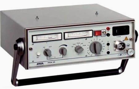
The DC HV 25kV Tester, Model No. PGK 25 manufactured by BAUR Germany. The test is applied only to cables covered with conductive layer over outer sheath. (Read more about Hipo Testing)
Instructions
- The covering under sheath is exposed about 2 cm length at one end of the cable so that the negative polarity shall be applied to it.
- The conductive layer on outer sheath shall be removed about 20 cm wide at a distance of 30 cm from both ends of the cable.
- The positive terminal of the DC source is connected to a copper band wound on the conductive layer of the sheath at one end of the cable (60 cm away from the end).
- The 25 kV tester can be operated by choice either from the power supply source of 220/110 v- 50/60 Hz supply or can be charging its in-built battery set-up.
- Switch on the timer in clockwise direction, a lamp indicator will be indicated ‘ON’ position to a desired test period.
- Select the voltage selector switch to 5 kV or 25 kV.
- Select the range of current measurement to position corresponding to the current value intended for charging the test cable.
- Slowly rotate the voltage selector to the desired voltage value on the scale (1 kV per second in intervals). Watch carefully the voltmeter while charging. If required re-adjust voltage selector before the desire test voltage is reached.
- Set range switch for current measurement to the desire range after charging has been completed.
- After the time has elapsed the high voltage bring down to zero, switch off the timer and discharge the cable through ground wire.

Requirements
The cable is considered to have passed if it withstands the required voltage (10 kV) during the test for 1 minute without break down. During the test, the leakage current shall be recorded. During the testing, safety regulations on electric hazards should be strictly observed. The measurements / reading are recorded in the available format in company.
5. Insulation resistance measurement
The insulation resistance shall be measured between conductor and metallic screen according to IEC 60840.
References
- IEC 60229 – Electric cables – Tests on extruded oversheaths with a special protective function
- TES-P-104.08 – Bonding and grounding of insulated metallic sheath of power cable system
Equipment / instruments used
Battery operated -KYORITSU High Voltage Insulation Resistance Tester, and MODEL-3125.

Instructions
- Cable should be free from all system connections
- Connect the cables between conductor and metal sheath.
- Measure the resistance at the required voltage and charging time (1 minute).

The insulation resistance (Ri) measured between each individual conductor and metal sheath. The insulation resistance per kilometer is calculated from:
Rl = Ri x L (GΩ Km)
Where:
Rl – Insulation resistance in GΩ Km.
Ri – Measured insulation resistance in GΩ.
L – cable length in Km.
6. Cross bonding check
With the cross bonding checks, the right connection of the cables can be checked and when correctly bonded, no current may flow in the metal sheath of the cable in case of an ideal situation.
The actual site requirements and situation dictate what the actual cable section lengths that may differ from section to section.
Equipment / Instruments used
- 380 V Generator
- 3-Phase Current Transformer
- Clamp Meter
Instructions
- Screen is to be grounded at both ends.
- The conductors are short circuited at the far end firmly by minimum 95 mm2 cable.
- The conductors under test are connected as shown in figure below.
- Increase the current gradually insteps by balancing the phases individually to desired value.
- Note down the current induced in all the link boxes.
- Reduce the current gradually and switch off the breaker.

Will be continued soon…
Related electrical guides & articles


Zafar Iqbal
Electrical engineer with more then 5 year experience in Electrical Transmission and Distribution Field. Highly specialized for design, installation and testing of HV/MV T&D lines and Power Substations.Profile: Zafar Iqbal

Hi Zafar,
Hope you are doing well,
How can I connect you sir? I have some questions regarding cable system?
Your kind and earliest reply shall be highly appreciated.