
Estimated Study Time: 21 minutes
Transmission line protection
As you already know, the real purpose of transmission line protection is to detect faults or abnormal operating conditions and to initiate corrective action. Protective relays must be able to evaluate a lot of parameters to choose and establish right corrective action. Obviously, a relay cannot prevent the fault.
 What's really important to achieve in transmission line protection relaying?
Its primary purpose is to detect the fault and take the necessary action to minimize the damage to the equipment or to the system.
The most common parameters which reflect the presence of a fault are the voltages and currents at the terminals of the protected apparatus or at the appropriate zone boundaries.
This problem is compounded by the fact that ‘normal’ in the present sense means outside the zone of protection. This aspect, which is of the greatest significance in designing a secure relaying system, dominates the design of all protection systems.
The Nature of Relaying
Let’s say a word about the most important considerations for transmission line protection:
1. Reliability
Reliability, in system protection parlance, has special definitions which differ from the usual planning or operating usage. A relay can misoperate in two ways: it can fail to operate when it is required to do so, or it can operate when it is not required or desirable for it to do so.
To cover both situations, there are two components in defining reliability:
- Dependability – which refers to the certainty that a relay will respond correctly for all faults for which it is designed and applied to operate.
- Security – which is the measure that a relay will not operate incorrectly for any fault.
Most relays and relay schemes are designed to be dependable since the system itself is robust enough to withstand an incorrect trip-out (loss of security), whereas a failure to trip (loss of dependability) may be catastrophic in terms of system performance.
2. Zones of Protection
The property of security is defined in terms of regions of a power system – called zones of protection for which a given relay or protective system is responsible. The relay will be considered secure if it responds only to faults within its zone of protection.
Figure 1 shows typical zones of protection with transmission lines, buses, and transformers, each residing in its own zone. Also shown are ‘‘closed zones’’ in which all power apparatus entering the zone is monitored, and ‘‘open’’ zones, the limit of which varies with the fault current.
Closed zones are also known as ‘‘differential,’’ ‘‘unit,’’ or ‘‘absolutely selective,’’ and open zones are ‘‘non-unit,’’ ‘‘unrestricted,’’ or ‘‘relatively selective.’’
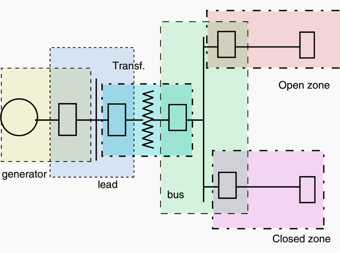
The zone of protection is bounded by the current transformers (CT) which provide the input to the relays. While a CT provides the ability to detect a fault within its zone, the circuit breaker (CB) provides the ability to isolate the fault by disconnecting all of the power equipment inside its zone.
When a CT is part of the CB, it becomes a natural zone boundary.
When the CT is not an integral part of the CB, special attention must be paid to the fault detection and fault interruption logic. The CTs still define the zone of protection, but a communication channel must be used to implement the tripping function.
Power Systems Protection (CT’s VT’s)
3. Relay Speed
It is, of course, desirable to remove a fault from the power system as quickly as possible. However, the relay must make its decision based upon voltage and current waveforms, which are severely distorted due to transient phenomena that follow the occurrence of a fault.
The relay must separate the meaningful and significant information contained in these waveforms upon which a secure relaying decision must be based. These considerations demand that the relay take a certain amount of time to arrive at a decision with the necessary degree of certainty.
Although the operating time of relays often varies between wide limits, relays are generally classified by their speed of operation as follows:
- Instantaneous — These relays operate as soon as a secure decision is made. No intentional time delay is introduced to slow down the relay response.
- Time-delay — An intentional time delay is inserted between the relay decision time and the initiation of the trip action.
- High-speed — A relay that operates in less than a specified time. The specified time in present practice is 50 milliseconds (3 cycles on a 60 Hz system).
- Ultra high-speed — This term is not included in the Relay Standards but is commonly considered to be operation in 4 milliseconds or less.
4. Primary and Backup Protection
The main protection system for a given zone of protection is called the primary protection system. It operates in the fastest time possible and removes the least amount of equipment from service.
On Extra High Voltage (EHV) systems, i.e., 345kV and above, it is common to use duplicate primary protection systems in case a component in one primary protection chain fails to operate. This duplication is therefore intended to cover the failure of the relays themselves. One may use relays from a different manufacturer, or relays based on a different principle of operation to avoid common-mode failures.
The operating time and the tripping logic of both the primary and its duplicate system are the same.
On lower voltage systems, even the relays themselves may not be duplicated. In such situations, a backup set of relays will be used. Backup relays are slower than the primary relays and may remove more of the system elements than is necessary to clear the fault.
4.1 Remote Backup Protection
These relays are located in a separate location and are completely independent of the relays, transducers, batteries, and circuit breakers that they are backing up. There are no common failures that can affect both sets of relays.
NOTE! However, complex system configurations may significantly affect the ability of a remote relay to ‘‘see’’ all faults for which backup is desired. In addition, remote backup may remove more sources of the system than can be allowed.
Figure 2 shows the single-line diagram for a network with a remote backup protection.
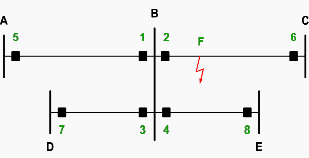
Here, a shunt fault occurs at F on the power line to C, and the line protection 2 at substation B fails to operate. The line protections 5, 7 and 8 have to detect the shunt fault at F. They also have to trip the breakers at A, D and E.
Distance protections and residual overcurrent protections provide remote backup protection on many networks.
4.2 Local Backup Protection
These relays do not suffer from the same difficulties as remote backup, but they are installed in the same substation and use some of the same elements as the primary protection. They may then fail to operate for the same reasons as the primary protection.
In case of local backup, there’s a distinction between substation local backup and circuit local backup. A circuit local backup protection senses the same current and voltage as the main protection. A substation local backup protection uses another current transformer than the main protection.
4.2.1 Substation Local Backup Protection
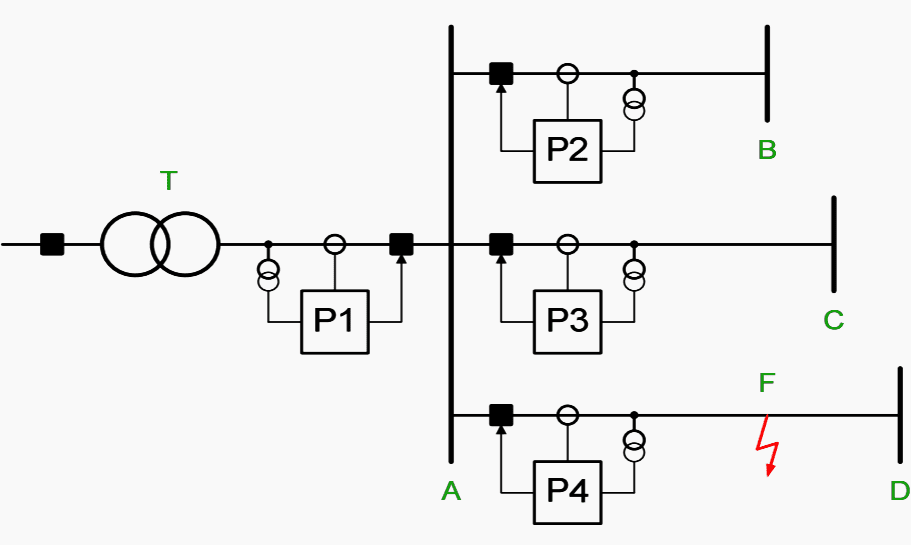
Figure 3 illustrates the concept of substation local backup protection. The HV-transformer T feeds the busbar A in a non-effectively earthed radial network without any other sources.
It is assumed that a short circuit occurs at F on the feeder to D and that the feeder protection P4 fails to operate. It is also assumed that the transformer protection P1 can detect short circuits along any feeder connected to the busbar A.
Substation local backup protection becomes difficult if one feeder connected to the busbar A is very long or if the transformer T has a high rated capacity.
4.2.2 Circuit Local Backup Protection
Remote backup cannot always detect all faults on the adjacent power lines. One example is a meshed HV network as shown in Figure 2 above.
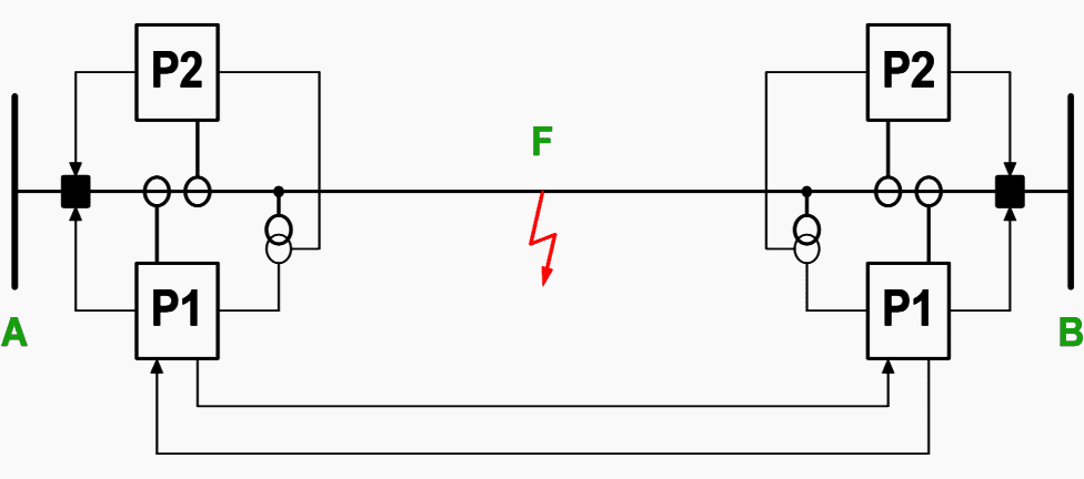
It is assumed that a shunt fault occurs at F on the power line between B and C and that the line protection 2 in substation B fails to operate. The line protections 5, 7 and 8 have to detect the shunt fault. The intermediate infeed at B will enlarge the impedances seen by the distance protections at A, D and E. This enlargement may prevent the use of remote backup protection.
The circuit local backup protection P2 comprises one delayed overcurrent relay and one delayed under-impedance relay. The non-directional overcurrent relay detects short circuits close to the substation.
The under-impedance relay shall detect short circuits along the entire line.
5. Reclosing
Automatic reclosing (AR) infers no manual intervention but probably requires specific interlocking such as a full or check synchronizing, voltage or switching device checks, or other safety or operating constraints.
Automatic reclosing (AR) can be high speed or delayed.
High Speed Reclosing (HSR) allows only enough time for the arc products of a fault to dissipate, generally 15–40 cycles on a 60 Hz base, whereas time delayed reclosings have a specific coordinating time, usually 1 or more seconds. HSR has the possibility of generator shaft torque damage and should be closely examined before applying it.
This practice has some applications in the U.S., but only in rare situations. When one phase of a three-phase system is opened in response to a single phase-toground fault, the voltage and current in the two healthy phases tend to maintain the fault arc after the faulted phase is de-energized.
Depending on the length of the line, load current, and operating voltage, compensating reactors may be required to extinguish this ‘‘secondary arc.
How it works | AR-Sequence
After the occurrence of a fault, the circuit breaker will be tripped by the protection functionality of the protected feeder followed by an automatic reclosing or an AR-shot, which is a function where the circuit breaker is automatically reclosed after a set time delay.
The purpose of this action is to return the status of the protected feeder automatically and in minimum time to its pre-fault, normal operating state.
If after the closing of the circuit breaker the fault has disappeared, the AR-shot was successful and the objective has been reached, see Figure 5.
the 2nd AR-shot is successful, bottom: both AR-shots fail, ”I” = CB closed, ”O” = CB
open
But if the fault still persists, the circuit breaker will be tripped again, and a new AR-shot will be made, as also, Figure 5. The operation continues like this until a predefined number of AR-shots have been performed.
Performing of the AR-sequence is typically controlled by a separate trip counter or a shot pointer function. Prior to the initiation of the 1st shot, the shot pointer has the value of one.
After completing of each shot, the shot pointer is set on such a value that the initiation of the shot just done and the shots whose sequence number is lower than that of the current one is not possible.
6. System Configuration
Although the fundamentals of transmission line protection apply in almost all system configurations, there are different applications that are more or less dependent upon specific situations.
6.1 Operating Voltages
Transmission lines will be those lines operating at 138 kV and above, subtransmission lines are 34.5 kV to 138 kV, and distribution lines are below 34.5 kV. These are not rigid definitions and are only used to generically identify a transmission system and connote the type of protection usually provided.
The higher relay costs, therefore, are more easily justified.
6.2 Line Length
The length of a line has a direct effect on the type of protection, the relays applied, and the settings. It is helpful to categorize the line length as ‘‘short,’’ ‘‘medium,’’ or ‘‘long’’ as this helps establish the general relaying applications although the definition of ‘‘short,’’ ‘‘medium,’’ and ‘‘long’’ is not precise.
A short line is one in which the ratio of the source to the line impedance (SIR) is large (>4 e.g.), the SIR of a long line is 0.5 or less and a medium line’s SIR is between 4 and 0.5.
It must be noted, however, that the per-unit impedance of a line varies more with the nominal voltage of the line than with its physical length or impedance. So a ‘‘short’’ line at one voltage level may be a ‘‘medium’’ or ‘‘long’’ line at another.
6.3 Multiterminal Lines
Occasionally, transmission lines may be tapped to provide intermediate connections to additional sources without the expense of a circuit breaker or other switching device.
The difficulty arises from the fact that a relay receives its input from the local transducers, i.e., the current and voltage at the relay location.
Referring to Figure 6, the current contribution to a fault from the intermediate source is not monitored.
The total fault current is the sum of the local current plus the contribution from the intermediate source, and the voltage at the relay location is the sum of the two voltage drops, one of which is the product of the unmonitored current and the associated line impedance.

References //
- Transmission Line Protection by Stanley H. Horowitz
- Power System Protection Practices: Backup protection by ABB
- Power System Protection Practices: Automatic reclosing by ABB
Related electrical guides & articles


Edvard Csanyi
Hi, I'm an electrical engineer, programmer and founder of EEP - Electrical Engineering Portal. I worked twelve years at Schneider Electric in the position of technical support for low- and medium-voltage projects and the design of busbar trunking systems.I'm highly specialized in the design of LV/MV switchgear and low-voltage, high-power busbar trunking (<6300A) in substations, commercial buildings and industry facilities. I'm also a professional in AutoCAD programming.
Profile: Edvard Csanyi

what is the specific resistance of copper in ohmic millimeter
The resistivity -or specific resistance- of copper is 1.67×10^-8 in S.I. units (ohm metres).
In cgs units (ohm centimetres) it is 1.67×10^-6.
in ohm millimetres (if you really need such a unit) it’s 1.67×10^-5.
These values are for a standardized temperature of 25C. For other ordinary temperatures the correction factor is very small (approx. 0.43% for each degree of temp change). As you no doubt know, for metals the resistivity decreases with decreasing temperature.
Interestingly, for copper. it never reaches zero even at absolute zero temperature. i.e. copper never becomes superconducting.
In fig. 6, the first equation in red lettering should of course read “If = I1+I2” (with 1 2 & f as subscripts).
In fig. 5, the sequence of colored blobs is shown as identical for both the middle & the bottom line (probably not what the author intended).