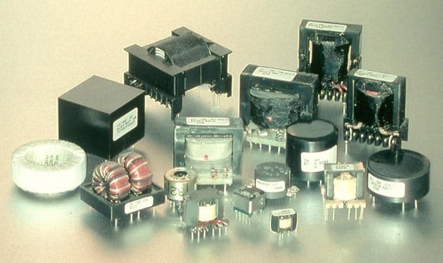
Instrument transformers
Instrument transformers are primarily used to provide isolation between the main primary circuit and the secondary control and measuring devices. This isolation is achieved by magnetically coupling the two circuits. In addition to isolation, levels in magnitude are reduced to safer levels.
Instrument transformers are divided in to two categories: voltage transformers (VT) and current transformers (CT). The primary winding of the VT is connected in parallel with the monitored circuit, while the primary winding of the CT is connected in series.
The secondary windings proportionally transform the primary levels to typical values of 120 V and 5 A. Monitoring devices such as wattmeters, power-factor meters, voltmeters, ammeters, and relays are often connected to the secondary circuits.
Voltage transformer (VT)
The voltage transformer (VT) is connected in parallel with the circuit to be monitored. It operates under the same principles as power transformers, the significant differences being power capability, size, operating flux levels, and compensation. VTs are not typically used to supply raw power; however, they do have limited power ratings.
They can often be used to supply temporary 120-V service for light-duty maintenance purposes where supply voltage normally would not other wise be available. In switchgear compartments, they may beused to drive motors that open and close circuit breakers.
In voltage regulators, they may power a tap-changing drive motor. The power ranges are from 500 VA and less for low-voltage VT, 1–3 kVA for medium-voltage VT, and 3–5 kVA for high-voltage VT. Since they have such low power ratings, their physical size is much smaller. The performance characteristics of the VT are based on standard burdens and power factors, which are not always the same as the actual connected burden.
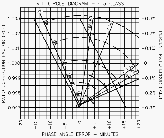
It is possible to predict , graphically, the anticipated performance when given at least two reference points. Manufacturers typically provide this data with each VT produced. From that, one can construct what is often referred to as the VT circle diagram, or fan curve, shown in Figure 1.
Knowing the ratio-error and phase-error coordinates, and the values of standard burdens, the graph can be produced to scale in terms of VA and power factor. Other power-factor lines can be inserted to pinpoint actual circuit conditions.

Performance can also be calculated using the same phasor concept by the following relationships, provided that the value of the unknown burden is less than the known burden.
Two coordinates must be known: at zero and at one other standard burden value.
REFERENCE: Instrument Transformers – Randy Mullikin


You write very clearly, really I appreciate it. I am interested to know, is it possible to megger a live wire or only way to measure in offline or disconnecting the line. If you have any post related this, please let me know. In my spare time I try to write in wazipoint.blogspot.com
i need to know how many phases are used for connecting current transformer and potential transformer..
Dear Sir,
Please share the method to calculate the rated verden of 69KV, Class 0.3 Potential Transformer for metering