
Factory tests
The remainder of the twelve factory tests are briefly summarized below. The details of the test set connections and formulas of some of the listed tests are already described in separatly published articles, and for the rest you are directed to ANSI/IEEE Standard C57.12.90 for these details.
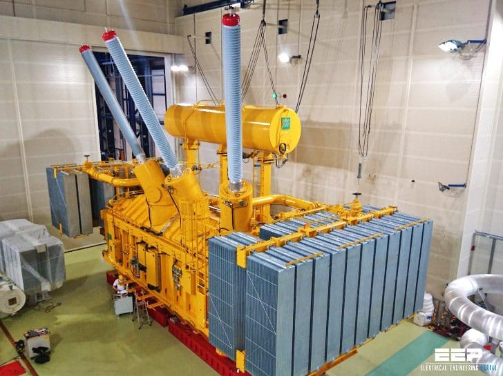 12 Transformer Factory Tests Briefly Explained (on photo: 420 kV power transformer, rated power 400 MVA produced by KOLEKTOR ETRA; transformer total mass is more than 400 ton and it operates in power plant in Germany, owned by SWM Infrastruktur GmbH.)
This list is not complete, there are few tests missing, not mentioned here, like Turn ratio test or Measurement of voltage ratio and check of phase displacement, but you can find them also separatly published at EEP (use Search).
- No-Load Losses
- No-Load Excitation Current
- Load Losses and Impedance Voltage
- Dielectric Tests
- Switching Impulse Test
- Lightning Impulse Test
- Partial Discharge Test
- Insulation Power Factor
- Insulation Resistance
- Noise Measurement
- Temperature Rise (Heat Run)
- Short-Circuit Test
1. No-Load Losses
The tests measures the no-load losses at specified excitation voltage and a specified frequency. Sine-wave voltages are used unless a different waveform is inherent in the operation of the transformer.
The test voltage is adjusted to the specified value as read by the average-responding voltmeters. The readings of both voltmeters are used to correct the no-load losses to a sine-wave basis.

2. No-Load Excitation Current
This current is measured in the winding used to excite the transformer with the other windings open-circuited. It is generally expressed in percent of the rated current of the winding. No-load excitation current is not sinusoidal and contains, as we have seen, odd harmonics (predominantly third harmonic current).
The ammeter used to record the no-load excitation current is an RMS meter which reads the square root of the sum of the squares of the harmonic currents.
3. Load Losses and Impedance Voltage
The transformer must be in a specific state before the load losses and impedance voltage are measured. The temperature of the insulating liquid must be stabilized and the difference between the top and bottom oil temperatures shall be less than 5°C.
The two test methods for measuring load losses and impedance voltage are:
- Wattmeter-voltmeter-ammeter method and
- Impedance bridge method.

These tests generally apply a reduced voltage to one set of windings with the other set of windings short-circuited. For three-winding transformers, these tests are repeated for each combination of windings taken two at a time.
4. Dielectric Tests
These tests consist of applied-voltage tests and induced-voltage tests.
Applied-voltage tests apply a high voltage to all bushings of a winding, one winding at a time, with the other windings grounded. A 60 Hz voltage is increased gradually over 15 s and held for 40 s and reduced to zero over 5 s.
Induced-voltage tests apply a high voltage across a winding with the other windings open-circuited in order to test the quality of the turn-to-turn insulation. In order to prevent core saturation at the higher excitation voltage, the frequency of the induced-voltage test is increased (typically around 120 Hz). The induced voltage is applied for 7200 cycles or 60 s, whichever is shorter.
5. Switching Impulse Test
The switching impulse test applies a switching impulse wave between each high-voltage line terminal and ground.
The test series consists of one reduced voltage wave (50%– 70% of specified test level) followed by two full-voltage waves. Either positive or negative polarity waves, or both, may be used. A voltage oscillogram is taken for each applied wave. The test is successful if there is no sudden collapse of voltage. Successive oscillograms may differ because of the influence of core saturation.

6. Lightning Impulse Test
The test sequence consists of one reduced full wave, two chopped waves, and two full waves. Tap connections are made with the minimum effective turns in the winding under tests and regulating transformers are set to the maximum buck position. Oscillograms are taken of each wave.
The general technique for interpreting the results is to look for differences in the shapes of the reduced full wave and the two full waves, which indicate turn-to-turn insulation failure.

Additional test criteria are found in IEEE Std. C57.98-1993. The impulse tests probably have the highest likelihood failures among all of the factory tests that are typically performed.
7. Partial Discharge Test
This test detects radio-frequency (0.85–1.15 MHz) noise generated from partial discharges within voids in the insulation. An applied voltage is gradually increased until partial discharge starts to occur, which is the inception voltage. The voltage is then decreased until the partial discharge stops, which is the extinction voltage.
The extinction voltage must be less than the operating voltage of the transformer; otherwise, once partial discharge starts in the field (due to some voltage transient), it would continue indefinitely and possibly cause damage or failure.

8. Insulation Power Factor
Insulation power factor is the ratio of the power dissipated in the insulation in watts to the apparent power (volt-amperes) under a sinusoidal voltage. The applied 60 Hz voltage of this test is generally lower than the operating voltage of the trans- former. The Doble Test Set is designed specifically to carry out this test.
Portable versions are used to measure the insulation power factor of transformers in the field. This test usually must be done by a trained technician. The test results are temperature-corrected to a reference temperature of 20°C.
9. Insulation Resistance
This test applies a high-voltage DC voltage to one winding at a time with the other windings grounded. The leakage current is measured and the insulation resistance is calculated using Ohm’s law.
10. Noise Measurement
The noise measurement test is carried out while the transformer is energized at rated voltage with all of the cooling equipment running. Room geometry can greatly affect the measurements, so it is preferable that the transformer be inside an anechoic chamber. However, if such a chamber is not available, no acoustically reflecting surface may be within 3 m of the measuring microphone other than the floor or ground.
The recording microphones are positioned in 1 m intervals around the perimeter of the transformer, with no fewer than four (4) microphone positions for small transformers..

Sound power levels are measured over a specified band of frequencies. The sound power levels are converted into decibels (dB).
11. Temperature Rise (Heat Run)
The transformer is energized at rated voltage in order to generate core losses. The windings are connected to a loading transformer that simultaneously circulates rated currents through all of the windings in order to develop load losses.
Naturally, the excitation voltage and the applied circulating currents are electrically 90° apart to minimize the KW requirements for this test. Nonetheless, a large power transformer can consume up to 1 MW of total losses and the heat run test is an expensive test to perform.
12. Short-Circuit Test
The short-circuit test is generally reserved for a sample transformer to verify the design of a core and coil assembly unless the customer specifies that a short-circuit test be performed on transformers that are purchased.
A low-voltage impulse (LVI) current waveform is applied to the transformer before and after the applications of short-circuit test. The ‘‘before’’ and ‘‘after’’ oscillograms of the LVI currents are compared for significant changes in waveshape that could indicate mechanical damage to the windings.
Reference // Power Transformers Principles and Applications – John J. Winders, Jr.
(Purchase from Amazon)


Hi, What tester you use for Induced voltage test?
Hi, I will like to know more details about the temperature rise test (Heat Run)
The Lightning impulse testing link is wrongly linked.
Searching the site you can find it easily enough, e.g.
Procedure for transformer lightning impulse test
https://electrical-engineering-portal.com/procedure-for-transformer-lightning-impulse-test
I just stumbled across this website and found it very informative. It is nice to know where to look if I have questions about required tests and testing equipment.
your GET ADOBE Service is not working
I would like to know basics that should be taken care off for electrifying commercial buildings