


Estimated Study Time: 26 minutes
132/33kV, 31.5MVA Transformer Protection
The provided schematics detail the comprehensive control, protection, metering, and operational logic for a 132/33kV, 31.5MVA Power Transformer (Transformer-1), explicitly designed by Schneider Electric for the APTRANSCO Thimmapuram substation.
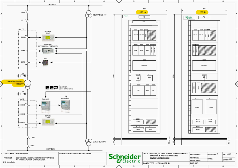 132/33kV, 31.5MVA Transformer Protection Schematics (PDF)
The architecture strictly segregates the high-voltage (132kV) and low-voltage (33kV) control environments into distinct panels, specifically designated as +1TR1A and +1TR1B.
This separation ensures that localized failures do not compromise the entire protection scheme. The system utilizes advanced Bay Control and Protection Units (BCPUs), high-speed master trip relays, redundant trip coils, and sophisticated numerical differential relay logic to guarantee absolute grid safety and ensure the longevity of the 31.5MVA transformer.
Here is the download link for the complete PDF document with 132/33kV, 31.5MVA transformer protection schematics (90 pages). Open it up, so you can follow the discussion.
Schematics (PDF, 1.6 MB)
- Panel Arrangement and Core IEDs
- Single Line Diagram (SLD) and Power Routing
- Core Protection Trip Logic Architecture
- Auxiliary Power Distribution (AC and DC)
- Differential Protection CT and PT Circuit Routing
- Opto-Isolated Inputs and Transducer Telemetry
- Master Trip and Local Breaker Backup (LBB) Execution Architecture
- Circuit Breaker Control Logic: Closing and Tripping Circuits
- Transformer Mechanical Troubles and Contact Multiplication
- Advanced BCPU Interlock Logics and IEC 61850 Automation
- Summary
- Attachment (PDF) 🔗 The Engineer’s Guide to Transmission Line Protection Applications
1. Panel Arrangement and Core IEDs
The physical layout of the +1TR1A panel is meticulously designed to optimize operator access while physically separating discrete protection zones.
Front View Arrangement (+1TR1A): As explicitly illustrated on Page 3 (Sheet 001), Row C, Columns 2-5, the front panel prominently features the MICOM P642 (87T) relay. This numerical relay serves as the brain for the Transformer Differential Protection.
Bay Control Unit: Flanking the differential relay is the BCPU-HV (C264P) unit (Page 3, Row C, Column 5). The C264P acts as a substation automation gateway, utilizing the IEC 61850 protocol to communicate via goose messages for non-directional overcurrent, earth fault protection, and localized automation.
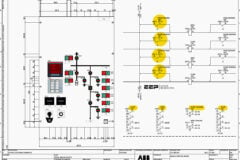
Figure 1 – Front view of the +1TR1A protection panel
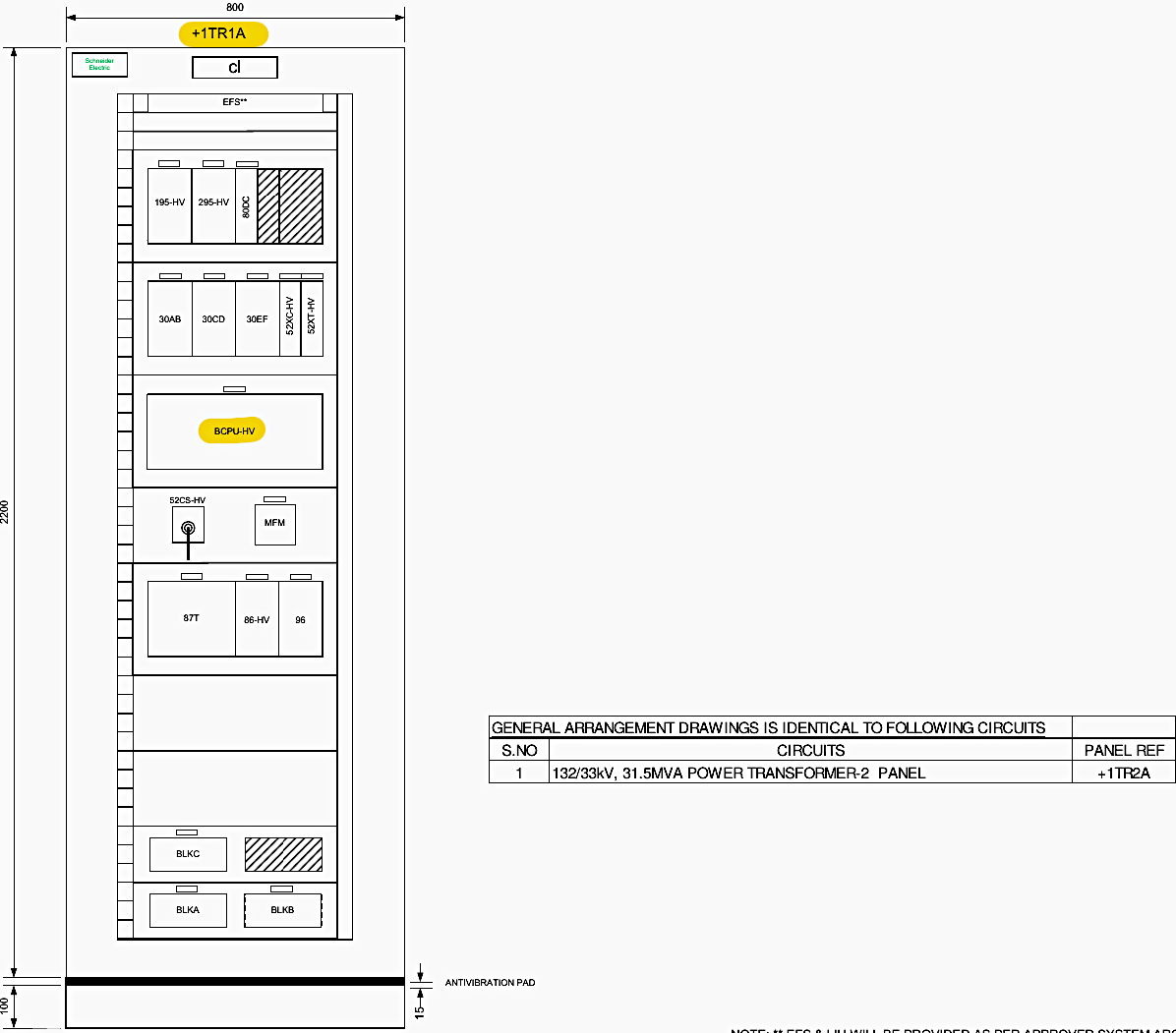
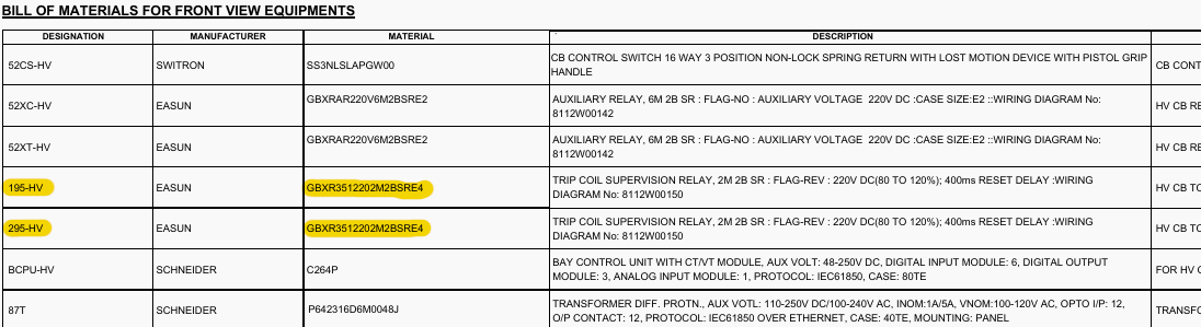
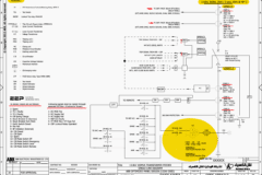
Electromechanical Trip Relays: Below the IEDs sit the Master Trip Relays (86-HV) and the Local Breaker Backup (LBB) Trip Relay (96). According to the Bill of Materials on Page 4, Row D, Column 3, the 86-HV and 96 relays are Easun GBTR241 high-speed, high-burden trip relays.
High-burden relays are critical because they require a significant amount of energy to operate, which prevents spurious trips caused by induced voltages or minor ground faults in the DC battery system.
Trip Coil Supervision: The Trip Coil Supervision Relays for the high-voltage side (195-HV and 295-HV) are identified as Easun GBXR351 models configured with a 400ms reset delay (Page 4, Row C, Column 1). These relays inject a tiny, continuous trickle current through the heavy-duty trip coils of the circuit breaker.
If the coil breaks or loses continuity, the relay drops out and triggers an alarm. The 400ms delay prevents the relay from initiating false alarms during the brief moment the circuit breaker successfully opens.
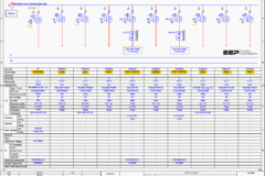
Figure 2 – Bill of materials for +1TR1A panel (TCS relays marked in yellow)
2. Single Line Diagram (SLD) and Power Routing
The macroscopic electrical routing and primary sensing equipment are mapped on the Single Line Diagram (Page 16).
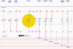
132kV Incomer and High Voltage Switchgear: The power flow originates at the 132KV BUS (Page 16, Row A, Column 1). It passes through the 189A Motorized Isolator (Page 16, Row A, Column 2). Isolators are off-load devices used to physically and visibly disconnect the transformer from the grid for maintenance.
Following the isolator is the 152 High Voltage Circuit Breaker (Page 16, Row A, Column 3). The circuit breaker is an on-load device containing SF6 gas to quench the massive electrical arc generated when breaking 132kV fault currents.
Figure 3 – 132kV side: 189A Motorized Isolator and 152 Circuit Breaker and CTs
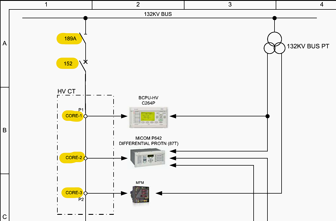
Current Transformers (CTs) – HV Side: Positioned immediately after the breaker are the HV CTs (Page 16, Row B, Column 2). These step down the massive primary currents to measurable secondary currents (1 Ampere) for the relays. The CTs feature three distinct cores to mathematically segregate duties:
- Core-1 (Class 5P20): Rated at 300-200-100/1A (Page 16, Row C, Column 6). The “5P20” designation means it guarantees 5% accuracy at 20 times the rated current. This core is wired directly to the BCPU-HV for standard overcurrent and earth fault protection.
- Core-2 (Class PS): This Protection Special (PS) core (Page 16, Row D, Column 6) is exclusively dedicated to the MICOM P642 Differential Protection.PS class CTs have highly specific knee-point voltages to ensure they do not saturate during heavy external faults, which could cause the 87T relay to falsely trip.
- Core-3 (Class 0.2): This core (Page 16, Row E, Column 6) interfaces with the metering circuits, guaranteeing 0.2% accuracy for billing and telemetry.
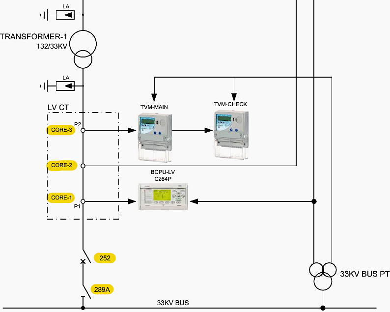
33kV Feeder and Low Voltage Switchgear: Power transforms and exits to the low voltage side, routing through the 33kV LV CTs (Page 16, Row D, Column 3). These utilize an identical three-core philosophy but with a stepped ratio of 1200-800-400/1-0.5775A to account for the increased current at the lower voltage.
Finally, power moves through the 252 LV Circuit Breaker and 289A LV Isolator before terminating at the 33KV BUS (Page 16, Row E, Column 4).
Figure 4 – 33kV side: Feeder CTs and 252 LV Circuit Breaker / 289A LV Isolator
3. Core Protection Trip Logic Architecture
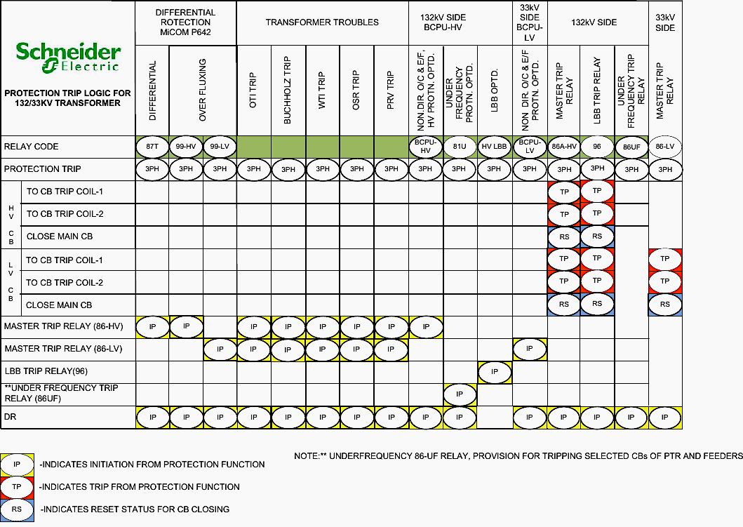
Page 17 establishes the critical Boolean logic mapping between fault detections and the resulting circuit breaker trip commands. This matrix dictates how the substation reacts to different classes of catastrophic failures.
Electrical Faults: The 87T Differential Protection (Page 17, Row B, Column 2) and the Over Fluxing Protection (99-HV/99-LV) are primary electrical safeguards.
Transformer Troubles (Mechanical and Thermal): The logic on Page 17, Row B, Column 4 defines how physical transformer distresses are handled.
Buchholz Relay: Detects gas accumulation from arcing in the oil. It maps directly to both the HV and LV master trip relays for a total, instantaneous shutdown.
Oil Surge Relay (OSR) and Pressure Relief Valve (PRV): These detect sudden, explosive pressure spikes inside the OLTC (On-Load Tap Changer) or main tank. They also map to both 86-HV and 86-LV for total isolation.
Temperature Indicators: Thermal overload indicators are localized to prevent unnecessary total grid loss. The WTI-HV (Winding Temperature Indicator – High Voltage) only trips the 86A-HV relay, while the WTI-LV isolates the 86-LV relay. Oil Temperature Indicators (OTI) trip both sides to allow the oil to cool rapidly.
Figure 5 – Core protection trip logic architecture matrix
4. Auxiliary Power Distribution (AC and DC)
A modern protection panel is useless without robust, redundant auxiliary power.
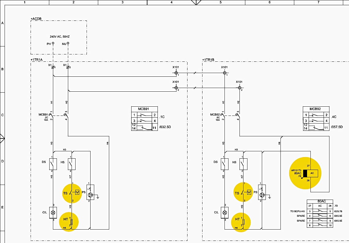
AC Distribution System: Detailed on Page 18 (Rows A-E), a 240V AC, 50Hz supply is distributed from the substation’s main +ACDB panel. A 16-Ampere Double Pole Miniature Circuit Breaker (MCB91) regulates the primary feed into the +1TR1A panel.
This power is not for protection; it drives environmental controls. The current flows to the panel heater (HT) through a mechanical thermostat (TS) (Page 18, Row E, Column 2). By maintaining a stable internal temperature, the thermostat prevents condensation from forming on the sensitive printed circuit boards of the numerical relays, which could cause devastating short circuits.
Furthermore, an 80AC supervision relay constantly monitors this voltage.
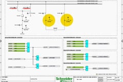
Figure 6 – AC auxiliary power distribution scheme
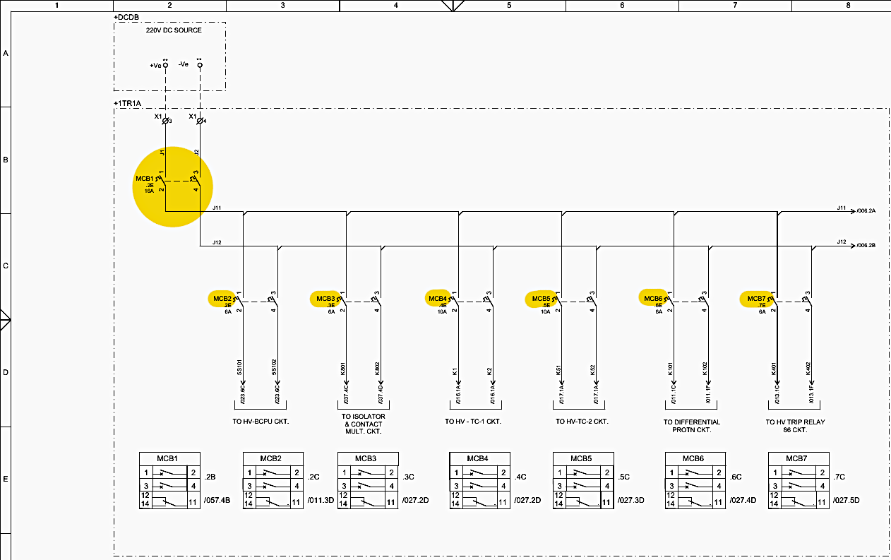
DC Distribution System: The critical 220V DC supply, drawn from a massive battery bank to ensure power during blackouts, is meticulously partitioned on Page 19 (Rows A-F). From the +DCDB source, current passes through a master 16A breaker (MCB1).
It is then aggressively subdivided into isolated radials. This subdivision is a core tenet of protection engineering: a single secondary fault must never blind the entire protection scheme.
- MCB4 (10A) exclusively feeds the HV CB Trip Coil 1 (TC-1) circuit (Page 19, Row C, Column 4).
- MCB5 (10A) provides redundant power to the HV CB Trip Coil 2 (TC-2) circuit (Page 19, Row C, Column 5).
- MCB6 (6A) strictly powers the MICOM P642 Differential Relay.
- MCB7 (6A) is dedicated solely to energizing the Master Trip Relay 86-HV.
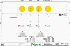
Figure 7 – DC auxiliary power distribution scheme
5. Differential Protection CT and PT Circuit Routing
The physics of differential protection require absolute synchronicity and accuracy between the primary high-voltage currents and secondary low-voltage currents.
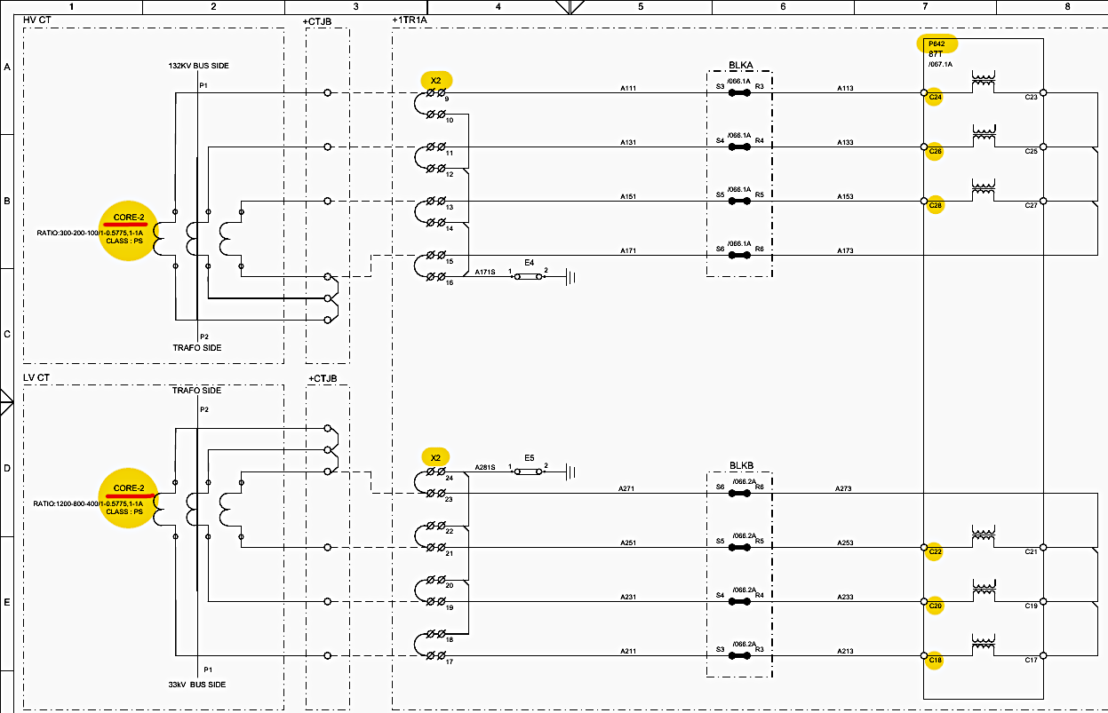
CT Wiring for 87T: Mapped on Pages 23 and 24, the secondary wires from the HV CTs (Core-2, Class PS) are routed from the switchyard to the panel. They pass through a specialized disconnecting test terminal block (X2) before reaching the MICOM P642 relay inputs C24, C26, and C28 (Page 23, Row C, Column 7).
The 33kV LV CTs are similarly routed to inputs C22, C20, and C18 (Page 23, Row D, Column 7).
Potential Transformer (PT) Extensions: The 132kV Bus PT circuit (Page 21) extends the 110V AC protection core (Core-1) via terminal block X3 directly to the BCPU-HV (Page 21, Row C, Column 8). This provides the bay controller with accurate grid voltage telemetry, essential for calculating power directionality, executing synchronization checks before closing the breaker, and generating undervoltage/overvoltage alarms.
Figure 7 – Differnetial protection CT & VT circuits
6. Opto-Isolated Inputs and Transducer Telemetry
Numerical relays and BCPUs rely on opto-isolators to safely read the status of high-voltage switchyard equipment.
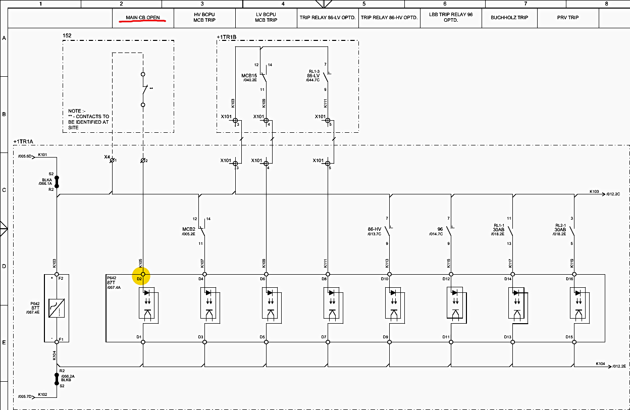
Differential Relay Opto-Inputs: Page 25 (Sheet 011) shows how 220V DC wet contacts interface with the MICOM P642. For example, the “MAIN CB OPEN” status is routed to opto-input D2 (Page 25, Row C, Column 2). When the breaker opens, a mechanical switch closes, sending 220V DC to terminal D2.
Inside the relay, this voltage lights an LED, which shines on a phototransistor. This optical gap physically protects the relay’s delicate 5V microprocessors from the 220V DC switchyard transients.
Figure 8 – Differential protection opto input circuit
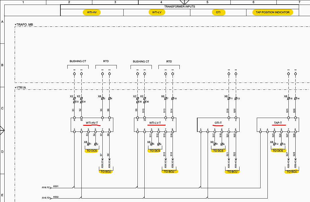
Analog Transducer Circuits: For continuous analog monitoring, Page 33 maps the routing of the Winding Temperature (WTI), Oil Temperature (OTI), and Tap Position transducers. The WTI-HV-T transducer receives dual inputs:
- Resistive Temperature Detector (RTD) submerged in the transformer oil, and
- Current feed from a Bushing CT.
By measuring both the base oil temperature and the current load, the transducer dynamically calculates the winding “hot-spot” temperature. It subsequently outputs an industry-standard 4-20mA analog signal to the Distributed Control System (DCS) and the BCPU (Page 33, Row C, Columns 2-4).
Figure 9 – Transducer circuit
7. Master Trip and Local Breaker Backup (LBB) Execution Architecture
When a fault is calculated, the numerical relays do not have the physical contact strength to break the high currents required by the switchyard circuit breaker trip coils. They rely on intermediate execution hardware.
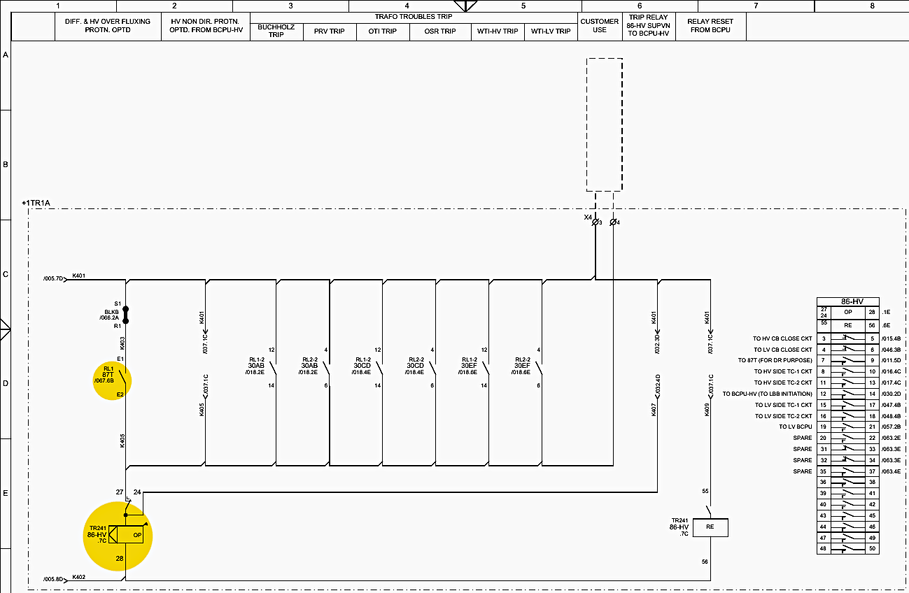
86-HV Master Trip Relay: Located on Page 27, this GBTR241 relay is the primary execution core for the 132kV side. It features a heavy-duty operation coil (OP) located at Page 27, Row E, Column 2. This coil is energized by the delicate contacts of the 87T relay (RL1), or mechanically driven auxiliary relays from the Buchholz, PRV, or OTI trips.
Simultaneously, normally-open contacts slam shut, driving 220V DC at high amperage directly to both the HV TC-1 and TC-2 trip coils. Because it mechanically latches, an operator must physically walk to the panel and manually reset the flag before the grid can be restored, ensuring the fault is investigated.
Figure 10 – HV master trip relay 86A-HV circuit
96 LBB (Local Breaker Backup) Relay: Documented on Page 28, the 96 relay logic addresses the nightmare scenario of a stuck breaker. If the differential relay issues a trip command, it simultaneously sends a start signal to the LBB timer inside the BCPU.
It instantly energizes the 96 relay coil (Page 28, Row C, Column 4). This relay bypasses the jammed breaker entirely, issuing an “OTHER BAY TRIP SIGNAL” (Page 28, Row B, Column 5) via terminal blocks X201 to the busbar protection panel.
This action trips every single incoming and outgoing breaker connected to the 132kV bus, isolating the jammed equipment and preventing a localized fire from triggering a cascading regional blackout.
Good Reading – Technical Analysis of BCU Logic in 132kV Line Protection Panel Schematics
Technical Analysis of BCU Logic in 132kV Line Protection Panel Schematics (Bay-B102)
8. Circuit Breaker Control Logic: Closing and Tripping Circuits
The control architecture is designed with heavy interlocking to prevent catastrophic operator errors, such as closing a breaker into a known fault or closing an isolator under load.
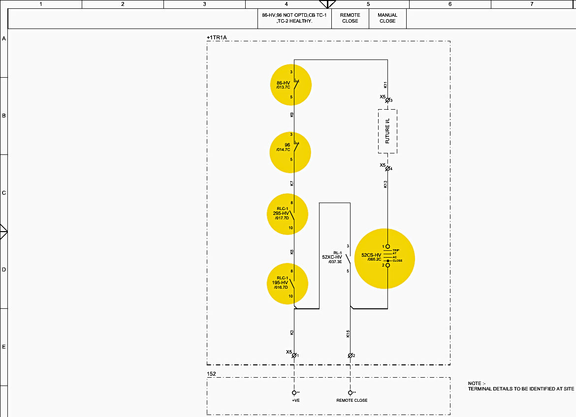
Closing Circuit (152 HV CB): Page 29 outlines the strict electrical interlocks required to safely close the primary 132kV breaker. The 220V DC must navigate a complex series of permissive contacts to complete the closing path to terminal X5 (Page 29, Row E, Column 4). The following conditions are absolutely mandatory:
- The 86-HV and 96 trip relays must be manually reset (verified by normally-closed contacts at Row C, Column 4).
- Both Trip Coil 1 and Trip Coil 2 must be verified as intact and healthy by the 195-HV and 295-HV supervision relays.
- The local/remote selector switch (52CS-HV) must be in the correct operational orientation.
If any single condition fails, the circuit physically cannot close.
Figure 11 – Circuit Breaker Control Logic: Closing and Tripping Circuits
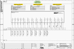
Tripping Circuits (HV TC-1 and TC-2): Redundancy is the defining characteristic of the tripping architecture on Pages 30 and 31. The TC-1 circuit (Page 30, Row C) provides multiple parallel pathways for the DC voltage to reach the trip coil. A trip can be initiated manually via the pistol grip switch (52CS-HV), remotely via SCADA (using the 52XT-HV relay), or automatically by the protective relays (96 or 86-HV).
The XR351 supervision relay constantly monitors the continuity of this coil circuit (Page 30, Row C, Column 6). Because the tripping circuit has fewer interlocks than the closing circuit (the breaker must always be allowed to trip, even if supervision fails), TC-2 (Page 31) acts as an identical, physically separate backup system fed from a different DC MCB.
Good Reading – Voltage transformer selection scheme in complex substations
9. Transformer Mechanical Troubles and Contact Multiplication
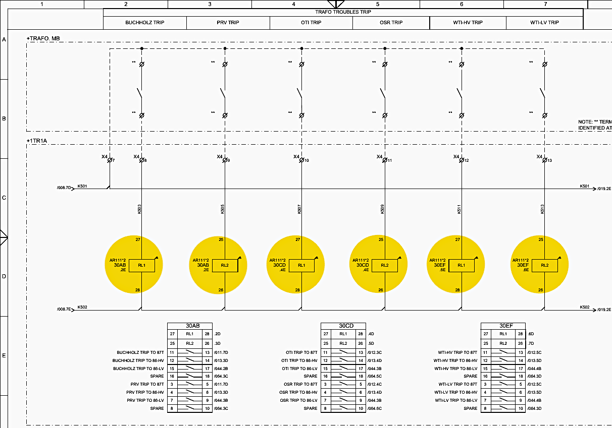
Mechanical fault signals originating from the transformer body (Buchholz gas sensors, Oil Surge Relays, Pressure Relief Valves) operate via small internal microswitches. These switches are low-current capable and would burn out if forced to directly drive heavy tripping coils.
Multiplying Auxiliary Relays: To solve this, the schematic utilizes “multiplying relays,” as demonstrated on Page 32. When a Buchholz float drops due to gas buildup, it sends a small signal to energize auxiliary relay 30AB (Page 32, Row D, Column 2).
This allows a single, fragile sensor on the transformer to safely provide a massive, multi-megawatt shutdown.
Figure 12 – Transformer trouble-auxiliary relay circuits
10. Advanced BCPU Interlock Logics and IEC 61850 Automation
Modern substations layer traditional hardwired electrical interlocks with programmable logic executed by the Bay Control Units (C264P). This allows for complex, network-aware safety checks that prevent operator errors that physical wiring alone cannot easily address.
189A Isolator Safety Logic: Page 89 outlines the Boolean logic governing the motorized 132kV isolator. Isolators do not have arc-quenching capabilities. If an isolator is opened while current is flowing, it will draw an unquenchable, vaporizing plasma arc that will destroy the switchyard.
Therefore, Page 89, Row B, Column 4 defines an AND gate that states the 189A isolator can only receive an “OPEN PERMISSIVE” or “CLOSE PERMISSIVE” command if the 152 Circuit Breaker is explicitly confirmed to be in the “OPEN” state (zero current flow). Furthermore, the bus earth switch must also be open.
Figure 13 – BCPU interlock logics
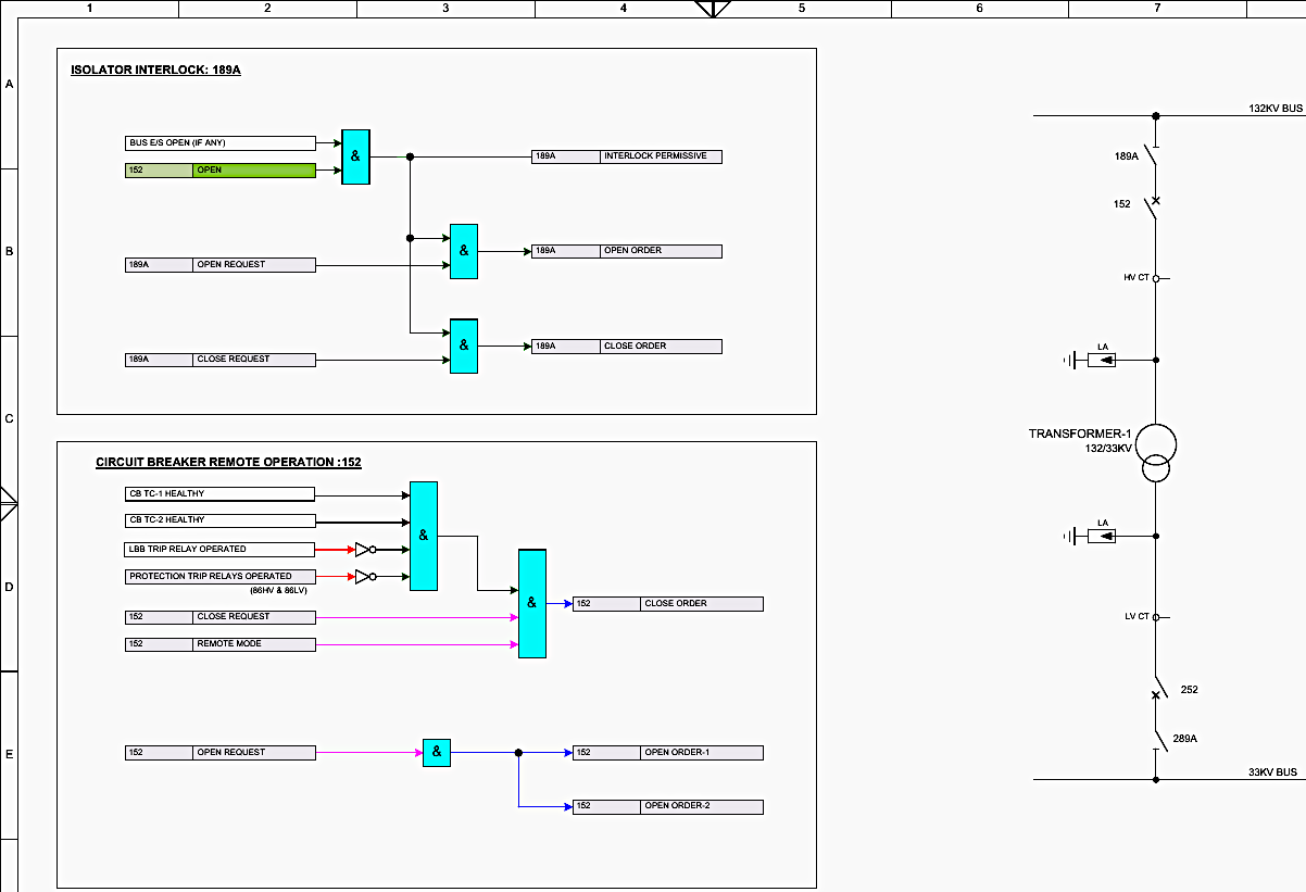
Remote Operation Interlocks (152 Breaker): To execute a remote SCADA close command on the 152 breaker (Page 74, Row C, Column 5), the BCPU relies on a massive internal Boolean AND gate.
The logic strictly requires that TC-1 is healthy, TC-2 is healthy, the LBB relay has not operated, no primary protection trip relays (86HV & 86LV) are currently operated or un-reset, and the Bay Local/Remote physical switch is explicitly set to Remote.
33kV Feeder Interlocks: Page 75 replicates this highly stringent automation logic for the 33kV side. The 289A Isolator is bound by identical no-load permissive rules, requiring the 252 LV Circuit Breaker to be open before movement is allowed (Page 75, Row B, Column 4).
The 252 LV CB close logic evaluates its own dedicated trip coils and the status of the 86-LV relay before permitting remote operations.
Recommended guide – A Guide to the Logic Behind the GIS Operation Interlocks
11. Summary
The Schneider Electric schematics for the APTRANSCO Thimmapuram 132/33kV transformer represent a masterclass in fail-safe electrical engineering. By layering hardwired electromechanical interlocks with programmable BCPU Boolean logic, carefully partitioning 220V DC power across completely isolated functional zones, employing three-core Current Transformers for perfect signal isolation, and deploying redundant trip coils supervised by dedicated heavy-duty relays, this blueprint guarantees an exceptionally resilient framework.
It is fundamentally designed to identify faults in milliseconds, clear them instantly through the master trip logic, and maintain total diagnostic visibility—ensuring that localized failures never result in catastrophic grid instability or the destruction of the power transformer.
12. Attachment (PDF): The Engineer’s Guide to Transmission Line Protection Applications
Download: The Engineer’s Guide to Transmission Line Protection Applications (for premium members only):
Related electrical guides & articles




Edvard Csanyi
Hi, I'm an electrical engineer, programmer and founder of EEP - Electrical Engineering Portal. I worked twelve years at Schneider Electric in the position of technical support for low- and medium-voltage projects and the design of busbar trunking systems.I'm highly specialized in the design of LV/MV switchgear and low-voltage, high-power busbar trunking (<6300A) in substations, commercial buildings and industry facilities. I'm also a professional in AutoCAD programming.
Profile: Edvard Csanyi
David, could you please advise me on the main references and methodology I should rely on for electrical drawing engineering, particularly for single-line diagrams?
It was really helpful, thanks
Good Information!
Dear Edvard
Please your help with my suscription, I can not enter EEP
Thank you very much
Hi Martin,
I already sent you an email with detailed instructions. Please, double check your email!
I am MGPathak graduate Electrical Engineer need job is there any vacancy Experience 21 yrs
Worked in Reliance petrochemical industry Nagothane Maharashtra