System Grounding Arrangement
The topic of system grounding is extremely important, as it affects the susceptibility of the system to voltage transients, determines the types of loads the system can accommodate, and helps to determine the system protection requirements.

The system grounding arrangement is determined by the grounding of the power source. For commercial and industrial systems, the types of power sources generally fall into four broad categories:
- Utility Service – The system grounding is usually determined by the secondary winding configuration of the upstream utility substation transformer.
- Generator – The system grounding is determined by the stator winding configuration.
- Transformer – The system grounding on the system fed by the transformer is determined by the transformer secondary winding configuration.
- Static Power Converter – For devices such as rectifiers and inverters, the system grounding is determined by the grounding of the output stage of the converter.
As a starting point, 18 key terms from the NEC need to be defined:
1. Ground
A conducting connection, whether intentional or accidental, between an electrical circuit or equipment and the earth or to some body that serves in place of the earth.

2. Grounded
Connected to earth or to some body that serves in place of the earth.
3. Effectively Grounded
Intentionally connected to earth through a ground connection or connections of sufficiently low impedance and having sufficient current-carrying capacity to prevent the buildup of voltages that may result in undue hazards to connected equipment or to persons.
4. Grounded Conductor
A system or circuit conductor that is intentionally grounded.
5. Solidly Grounded
Connected to ground without inserting any resistor or impedance device.
6. Grounding Conductor
A conductor used to connect equipment or the grounded circuit of a wiring system to a grounding electrode or electrodes.
7. Equipment Grounding Conductor
The conductor used to connect the non-current-carrying metal parts of equipment, raceways and other enclosures to the system grounded conductor, grounding electrode conductor, or both, at the service equipment or at the source of a separately-derived system.
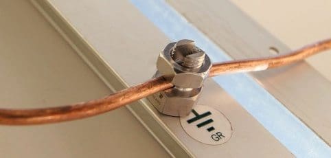
8. Main Bonding Jumper
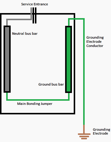
The connection between the grounded circuit conductor and the equipment grounding conductor at the service.
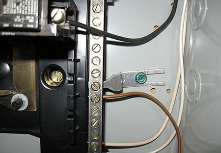
9. System Bonding Jumper
The connection between the grounded circuit conductor and the equipment grounding conductor at a separately-derived system.
10. Grounding Electrode
The conductor used to connect the grounding electrode(s) to the equipment grounding conductor, to the grounded conductor, or to both, at the service, at each building or structure where supplied by a feeder(s) or branch circuit(s), or at the source of a separately-derived system.
11. Grounding Electrode Conductor
The conductor used to connect the grounding electrode(s) to the equipment grounding conductor, to the grounded conductor, or to both, at the service, at each building or structure where supplied by a feeder(s) or branch circuit(s), or at the source of a separately-derived system.

12. Ground Fault
An unintentional, electrically conducting connection between an ungrounded conductor of an electrical circuit and the normally non-current-carrying conductors, metallic enclosures, metallic raceways, metallic equipment, or earth.
13. Ground Fault Current Path
An electrically conductive path from the point of a ground fault on a wiring system through normally non–current-carrying conductors, equipment, or the earth to the electrical supply source.
14. Effective Ground-Fault Current Path
An intentionally constructed, permanent, low-impedance electrically conductive path designed and intended to carry current under ground-fault conditions from the point of a ground fault on a wiring system to the electrical supply source and that facilitates the operation of the overcurrent protective device or ground fault detectors on high-impedance grounded systems.
15. Ground-Fault Circuit Interrupter

A device intended for the protection of personnel that functions to de-energize a circuit or portion thereof within an established period of time when a current to ground exceeds the values established for a Class A device.
16. FPN
Class A ground-fault circuit interrupters trip when the current to ground has a value in the range of 4 mA to 6 mA. More information can be found on UL 943, Standard for Ground-Fault Circuit Interrupters.
17. Ground Fault Protection of Equipment
A system intended to provide protection of equipment from damaging line-to-ground fault currents by operating to cause a disconnecting means to open all ungrounded conductors of the faulted circuit.
18. Qualified Person
One who has the skills and knowledge related to the construction and operation of the electrical equipment and installations and has received safety training on the hazards involved.
With these terms defined, several of the major components of the grounding system can be illustrated by Figure 1 and labeling the components.

Reference: System Grounding – Bill Brown, P.E., Square D Engineering Services





I am surprised to see a picture of a ground rod with a green/yellow ground conductor with a COIL. I believe that the coil will present a high impedance to a lightening discharge – especially with the initial stroke. Lightening does not like to take sharp turns and clearly the coil presents a continuous series of sharp turns. Am I off based here or do I make some sense?
David, I was going to say the exact same thing about the coil of wire at the ground rod!
When the sys type is tnc-s we connect the neutral bar to the earthing bar by(jumer) which should be in one point in all service area at the mdb which is connected to the earthing bit too.
sir you’re topics are incredible and very touchable in working area ,
actually i am stuck with standby generators grounding system , i wonder if you can provide a comprehensive topic about it and i appreciate if answering according to these points
1- type of utility source grounding 2- type of ATS 3 or 4 poles 3- type of earth fault protection 3- if any
very nice and useful information. keep on sharing. best luck
Honestly, I believe this is thd best resource thar answers my queries and inspires me to learn more of electrical engineering.
My areas are electronics and IT infrastructure. I’d just wish I could have these articles in Spanish for some engineerd here in México City.
This topic of Grounding is so vast! But, now, I feel like an ‘expert’!
In Spanish they use frases like :[sistema de] Tierrs Fisica, Aterrizaje , Puesta de Tierra.
Well keeo on writing, keep on sharing!
Thank you for this review of definitions used in the NEC. For #11 please add that the rod is required to be driven to a full 8 ft. depth, unless it is a 10 ft. rod.
That is correct. But judging on the bus bar in the picture… It looks like a neutral buss bar. I see no grounding wires going to it. (Green or green yellow). So I assuming its a neutral bus until corrected. A neutral to case bonding at places other than you meter or first disconnect causes neutral currents to flow on the metal parts. Stated by the NEC. If that bus is a grounding bus bar well the picture is showing the right
thing.
#10 – Grounding Electrode & #11 – Ground Electrode Conductor, both are showing same definitions. Is this correct?
I thinking the definition are for the ground electrode conductor only. Fig 10 need to explain what is the ground electrode itself.
Which is the conductor physically connected to the earth. Where the grounding electrode conductor whit be physically connect to the ground electrode to attain an earth connection.
The figure under main bonding jumper.
That figure under the main bonder is that bus bar a neutral or a ground bus bar? I see two white wires going to that bus. So I’m assuming that it’s a neutral bus now if that’s so i dont no think that picture is not correct. The bonding jumper to case should be on the grounding terminal bus. If you bond the case to the neutral bus you are creating objectional currents on all metal parts which is a hazard.
The main purpose of a bonding jumper is to ensure no differential exists between the pieces of equipment. In the example shown, if you had a problem inside the cabinet without the bonding jumper, there could be a voltage difference between the equipment inside and the cabinet. It is the same reason we put bonding jumpers between metal stairs and metal platforms in a power plant. To reduce the potential of electrical differential.