
Understanding motor’s nameplate
Motor nameplate is normally located on all produced electric motors. Understanding nameplate information can be hard sometimes, but is essential. In most countries it is a requirement for manufacturers to display all information on the motor’s nameplate, but often this is not the case.
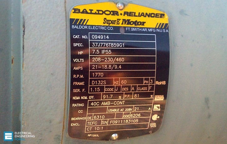 19 Essential Information Found On Motor’s Nameplate (on photo: Baldor Reliancer motor; credit: rickmcneely.com)
However, when a motor has been in operation for a long time, it is often not possible to determine its operating information because nameplates of motors are often lost or painted over.
- Voltage
- Frequency
- Phase
- Current
- Type
- Power factor
- kW or Horsepower
- Full-load speed
- Efficiency
- Duty
- Insulation class
- Maximum ambient temperature
- Altitude
- Enclosure
- Frame
- Bearings
- NEMA // Letter code
- NEMA // Design letter
- NEMA // Service factor
Electrical input //
1. Voltage
This data tells you at which voltage the motor is made to operate. Nameplate-defined parameters for the motor such as power factor, efficiency, torque and current are at rated voltage and frequency. When the motor is used at other voltages than the voltage indicated on the nameplate, its performance will be affected.
2. Frequency
Usually for motors, the input frequency is 50 or 60 Hz. If more than one frequency is marked on the nameplate, then other parameters that will differ at different input frequencies have to be indicated on the nameplate as well.
3. Phase
This parameter represents the number of AC power lines that supply the motor. Single-phase and three-phase are considered as the standard.
4. Current
Current indicated on the nameplate corresponds to the rated power output together with voltage and frequency. Current may deviate from the nameplate amperes if the phases are unbalanced or if the voltage turns out to be lower than indicated.
5. Type
Some manufacturers use type to define the motor as single-phase or poly-phase, single-phase or multi-speed or by type of construction. Nevertheless, there are no industry standards for type. Grundfos uses the following type designation: MG90SA2-24FF165-C2.
6. Power factor
Power factor is indicated on the nameplate as either “PF” or “P .F” or cos φ . Power factor is an expression of the ratio of active power (W) to apparent power (VA) expressed as a percentage.
The motor’s nameplate provides you with the power factor for the motor at full-load.
Mechanical Input //
7. kW or horsepower
kW or horsepower (HP) is an expression of the motor’s mechanical output rating – that is it’s ability to deliver the torque needed for the load at rated speed.
8. Full-load speed
Full-load speed is the speed at which rated full-load torque is delivered at rated power output. Normally, the full-load speed is given in RPM. This speed is sometimes called slip-speed or actual rotor speed.
Performance //
9. Efficiency
Efficiency is the motor’s output power divided by its input power multiplied by 100. Efficiency is expressed as a percentage. Efficiency is guaranteed by the manufacturer to be within a certain tolerance band, which varies depending on the design standard, eg IEC or NEMA.
Therefore, pay attention to guaranteed minimum efficiencies, when you evaluate the motor’s performance.
10. Duty
This parameter defines the length of time during which the motor can carry its nameplate rating safely. In many cases, the motor can do it continuously, which is indicated by an S1 or “Cont” on the nameplate. If nothing is indicated on the nameplate, the motor is designed for duty cycle S1.
Reliability
11. Insulation class
Insulation class (INSUL CLASS) is an expression of the standard classification of the thermal tolerance of the motor winding. Insulation class is a letter designation such as “B” or “F”, depending on the winding’s ability to survive a given operating temperature for a given life. The farther in the alphabet, the better the performance.
For instance, a class “F” insulation has a longer nominal life at a given operating temperature than a class “B”.
12. Maximum ambient temperature
The maximum ambient temperature at which a motor can operate is sometimes indicated on the nameplate. If not the maximum is 40°C for EFF2 motors and normally 60°C for EFF1 motors. The motor can run and still be within the tolerance of the insulation class at the maximum rated temperature.
13. Altitude
This indication shows the maximum height above sea level at which the motor will remain within its design temperature rise, meeting all other nameplate data.
Construction
14. Enclosure
Enclosure classifies a motor as to its degree of protection from its environment and its method of cooling. Enclosure is shown as IP or ENCL on the nameplate.
15. Frame
The frame size data on the nameplate is an important piece of information. It determines mounting dimensions such as the foot hole mounting pattern and the shaft height. The frame size is often a part of the type designation which can be difficult to interpret because special shaft or mounting configurations are used.
16. Bearings
Bearings are the component in an AC motor that requires the most maintenance. The information is usually given for both the drive-end (DE) bearing and the bearing opposite the drive-end, non drive- end (NDE).
NEMA
Besides the above mentioned information, NEMA nameplates have some supplementary information. The most important ones are:
- Letter code,
- Design letter and
- Service factor.
17. Letter code
A letter code defines the locked rotor current kVA on a per horsepower basis. The letter code consists of letters from A to V. The farther away from the letter code A, the higher the inrush current per horsepower.
| NEMA code letter | Locked rotor kVA/HP | NEMA code letter | Locked rotor kVA/HP |
| A | 0 – 3.15 | L | 9.0 – 10.0 |
| B | 3.15 – 3.55 | M | 10.0 – 11.2 |
| C | 3.55 – 4.0 | N | 11.2 – 12.5 |
| D | 4.0 – 4.5 | O | NOT USED |
| E | 4.5 – 5.0 | P | 12.5 – 14.0 |
| F | 5.0 – 5.6 | Q | NOT USED |
| G | 5.6 – 6.3 | R | 14.0 – 16.0 |
| H | 6.3 – 7.1 | S | 16.0 – 18.0 |
| I | NOT USED | T | 18.0 – 20.0 |
| J | 7.1 – 8.0 | U | 20.0 – 22.4 |
| K | 8.0 – 9.0 | V | 22.4 AND UP |
18. Design letter
Design letter covers the characteristics of torque and current of the motor. Design letter (A, B, C or D) defines the different categories. Most motors are design A or B motors.
So, when replacing a motor in an application, it is important to check the design letter, because some manufacturers assign their products with letters that are not considered industry standard which may lead to starting problems.
19. Service factor
A motor designed to operate at its nameplate power rating has a service factor of 1.0. This means that the motor can operate at 100% of its rated power.
Some applications require a motor that can exceed the rated power. In these cases, a motor with a service factor of 1.15 can be applied to the rated power. A 1.15 service factor motor can be operated at 15% higher than the motor’s nameplate power.
However, any motor that operates continuously at a service factor that exceeds 1 will have reduced life expectancy compared to operating it at its rated power.
Reference // Motor book by Grundfos (Download)


From the point of view I see this site to helpful were motors are concerned.
Edvard, Novice question here In regard to 3 phase motors: Is a measured RLA of around 27 amps on each line too high for a motor whose data tag list 30 amps?
Does a technician need to take a reading or average of 3 then multiply by 1.73 and compare this to the data tag? Or should no phase be operating above 30 amps + service factor?
I have an old mill and the nameplate has some info I’m not familiar with. In order it reads : H.P._ R.P.M._ FR. 254 VOLTS_ AMPS_ PH._ CYC 60. The info with number values are the two I’m unsure of. My best guess is that FR. is frequency and CYC is duty cycle? But I really don’t know :/
Hi Sean, the FR likely refers to the frame dimensions (25/4 = 6.25″ base to shaft) and CYC probably refers to the frequency or cycles per second which will be 60Hz in North America.
Frame and frequency
Does the voltage refer to line-to-line or line-to-neutral values?
Is the motor nameplate rated current the current in one phase leg or the sum of all three phase legs (current in one phase * 1.73)?
How to know motor is suitable for VFD operation from motor nameplate. Here in given nameplatethere is no info is mentioned about VFD operation.
How to know the quantity grease to fill in the bearing by reading the motor nameplate
1.What is the function of duty cycle on motor nameplate?
2. How to know the time to regrease a motor by reading it’s nameplate?
Good evening Sir. I have a question?How can a single phase motor can be made self starting
Single phase induction motor cant be self starting because in this motor when current induce in rotor(due to emf) then rotor experience a force but it can’t not decide direction to rotate (because rotor are inner part and both upper side like stator have a same magnetic field).in that case rotor create a hum sound when we give some torque on a particular direction then the rotor rotate start that direction by an auxiliary supply when rotor start rotate then auxiliary supply automatically disconnect and motor run properly
GOOD MORNING I NEED CROSSREFERENCE
120RU02H80X26 BALDOR RELLIANCE
110BT02J00X26 BALDOR RELLIANCE
How would you determine FLA with this info?
Is it safe or even allowed to apply higher voltage than the voltage indicated on the equipment name plate? Ex. Applying 480 volt to a 208 stamped nameplate?
Why would you do this? You could burn the windings…
Hi
Love your site…
There is a case its to do with the VF ratio
So you connect the motor in delta …but run on the star rated voltage. Then adjust the drives VF ratio to suit.
Its to do with delivering more torque above the nominal speed of the motor.
…I’ve seen this and done it. …but you are now working outside of the manufactures guidelines.
Not a commonly known trick and I’ve only seen it done twice….
Your dealing with an inverter so you can set max current trip etc etc..if you think it will cook the motor
can we determine motor shaft size from name plate?
I would like to praise you, and your associates! Your site provides a plethora of information. And your formatting of the subject matter; that you have made available for the public to use. Is easy to use and logically layed out.
Thank you Douglas!
Ditto on thank you.. for providing info to public.
I am an inventor/ innovator and often repurpose or convert or modify existing frames and designs. I respectfully request data base complication for alternate uses like universal motors which can run on DC or AC and permanent magnet motors and any unusual desigs and possible alterhet configurations etc new tech new designs and thots on them it would be a most helpful data base etc helping those if us without the resources or your type of exp and education.. in the interests of improving the world. Big companing nefa cotos etc always try to squelch any innovations that may reduce thier power control or profits/income. If I had a genie bottle wish it would be to reverse that and give them a conscious.. imagine the advancements possible if the money they put into stopping or hamstringing progress was instead spent helping .. so you could do alot with just data and pricing access to new ideas and theories. For instance RF induced hi volt low amp tech.. Tesla based won’t make big corps happy but is better technology. And I’m working in using back emf pulses to increase windmill generation of electricity .. I’m hoping up to 350% for the same size frame and rotor. Current/present designs suck ass. Old views.. well that’s my 3¢.. idea: you could do this as a tax right off giving back to community.. thsnx have a great day. I could use r&d funding too🙃 can’t hurt to ask Right!?
very good
Thanks for the informationa
Thank you for clear and complete information.it was so useful and help me to inspect the Siemens motors and also prepare a professional report.
You’re welcome Amin.
Hi, My comment regarding the voltage is that how can we identify if this is applicable for wye delta controls.
Hi …. Can you tell me what the letters CY stand for on a GE Motor 1/4hp AC 230v single phase motor. It has CY in red and then the number 50 stamped in black ? Thank you, Ady
Thank you Edvard for this information and I wish to learn more from you.
Great knowledge sharing. Thanks..Good luck for future.
Its great information about a motor thanx for ur data. I am waiting for your app in windows phone pls consider this request….
Thanks edward
Really Amazing Informations sir …
Very helpful …
The information contained on your site is excellent and I am very happy with the articles provided.
Very important information thanks can provide us test type can carry on motor LV and HV voltage
Thanks to provide such a useful info.hopping for continuous do your best
You’re welcome Sagar.
Dear sir,
Thanks for this invaluable information which is very important for engineers dealing with electric motors.
In item number 5 I think you mean single speed please correct if I am right.
Also I think the model and serial numbers for a certain manufacturer is important and is shown on the nameplate also what about motor cooling and information about the cooling fan.
You are welcome Sirelkhatim! Number 5 is actually internal type mark of manufacturer. Each motor manufacturer has its own labeling which is telling a lot of things about motor.