
Estimated Study Time: 8 minutes
Series Parallel Networks
A firm understanding of the basic principles associated with series and parallel circuits is a sufficient background to begin an investigation of any single-source DC network having a combination of series and parallel elements or branches. In general, series parallel networks are networks that contain both series and parallel circuit configurations.
 2 approaches to analyse and solve series parallel networks
One can become proficient in the analysis of series parallel networks only through exposure, practice, and experience. In time the path to the desired unknown becomes more obvious as one recalls similar configurations and the frustration resulting from choosing the wrong approach.
Getting started //
There are a few steps that can be helpful in getting started on the first few exercises, although the value of each will become apparent only with experience.
Step No. 1 Take a moment to study the problem “in total” and make a brief mental sketch of the overall approach you plan to use. The result may be time- and energy-saving shortcuts.
Step No. 2 Next examine each region of the network independently before tying them together in series-parallel combinations. This will usually simplify the network and possibly reveal a direct ap- proach toward obtaining one or more desired unknowns.
Step No. 3 Redraw the network as often as possible with the reduced branches and undisturbed unknown quantities to maintain clarity and provide the reduced networks for the trip back to unknown quantities from the source.
Step No. 4 When you have a solution, check that it is reasonable by considering the magnitudes of the energy source and the elements in the network. If it does not seem reasonable, either solve the circuit using another approach or check over your work very carefully.
Reduce and Return Approach //
For many single-source, series parallel networks, the analysis is one that works back to the source, determines the source current, and then finds its way to the desired unknown.
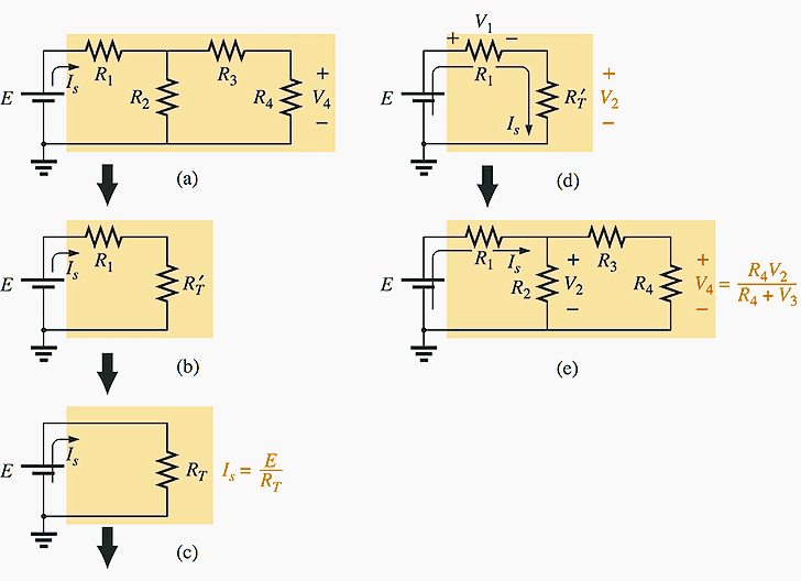
In Figure 1(a), for instance, the voltage V4 is desired. The absence of a single series or parallel path to V4 from the source immediately reveals that the methods introduced in the last two chapters cannot be applied here. First, series and parallel elements must be combined to establish the reduced circuit of Fig. 1(b). Then series elements are combined to form the simplest of configurations in Fig. 1(c).
The voltage V2 can be determined and then the original network can be redrawn, as shown in Fig. 1(e). Since V2 is now known, the voltage divider rule can be used to find the desired voltage V4. Because of the similarities between the networks of Figures 1(a) and 1(e), and between 1(b) and 1(d), the networks drawn during the reduction phase are often used for the return path.
Although all the details of the analysis were not described above, the general procedure for a number of series-parallel network problems employs the procedure described above: Work back for Is and then follow the return path for the specific unknown.
Not every problem will follow this path. Some will have simpler, more direct solutions. However, the reduce and return approach will handle one type of problem that does surface over and over again.
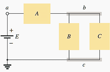
Block Diagram Approach //
To solve series parallel networks, the block diagram approach will be employed throughout to emphasize the fact that combinations of elements, not simply single resistive elements, can be in series or parallel. The approach will also reveal the number of seemingly different networks that have the same basic structure and therefore can involve similar analysis techniques.
Initially, there will be some concern about identifying series and parallel elements and branches and choosing the best procedure to follow toward a solution.
However, as you progress through the examples and try a few problems, a common path toward most solutions will surface that can actually make the analysis of such systems an interesting, enjoyable experience :)
In Figure 2, blocks B and C are in parallel (points b and c in common), and the voltage source E is in series with block A (point a in common). The parallel combination of B and C is also in series with A and the voltage source E due to the common points b and c, respectively.
For series resistors R1 and R2, a comma will be inserted between their subscript notations, as shown here //
![]()
For parallel resistors R1 and R2, the parallel symbol will be inserted between their subscript notations, as follows //
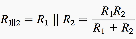
Parallel and Series Resistor Circuit Analysis
This procedure is tedious, but it requires very little fancy math and it’s conceptually beautiful. You ought to be able to look at the finished product and explain WHY the values of voltage drops and currents for each resistor and combination of resistors have the relationships they do.
Yay! You can now simplify any circuit with just one battery and a bunch of resistors!
Reference // Fundamentals of electrical engineering by Giorgio Rizzoni (Get it from Amazon)
Related electrical guides & articles


Edvard Csanyi
Hi, I'm an electrical engineer, programmer and founder of EEP - Electrical Engineering Portal. I worked twelve years at Schneider Electric in the position of technical support for low- and medium-voltage projects and the design of busbar trunking systems.I'm highly specialized in the design of LV/MV switchgear and low-voltage, high-power busbar trunking (<6300A) in substations, commercial buildings and industry facilities. I'm also a professional in AutoCAD programming.
Profile: Edvard Csanyi

Please add some basic concept to solve complex circuit and basic idea of to start to solve any complex circuit