


Estimated Study Time: 35 minutes
Analysis of the 204RP Panel
This article provides a systematic technical analysis of the 220kV Busbar and Bus Coupler Control and Relay Panel (C&R Panel, designated as 204RP) schematics for the 220/132kV Substation, executed by General Electric. The analysis follows the logical progression of the schematic drawings, beginning with the panel’s General Arrangement and Bill of Materials to establish the hardware baseline.
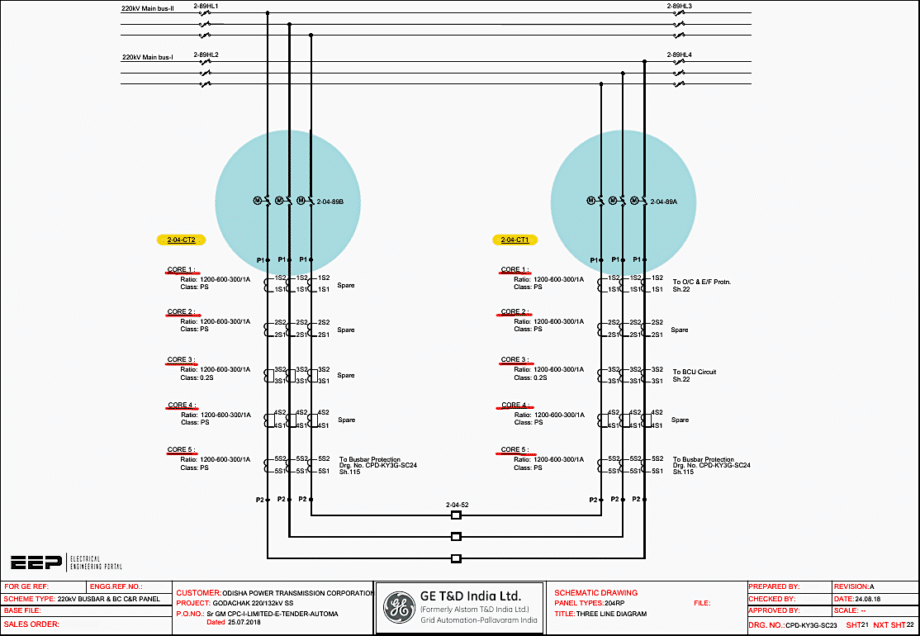 220kV Busbar and Bus Coupler Control and Relay Panel Schematics
It then reviews the auxiliary AC and DC distribution circuits utilized to power the panel’s logic relays, instrumentation, and protective devices. Subsequent sections examine the secondary circuits for the instrument transformers, including both Current Transformers (CT) and Inductive Voltage Transformers (IVT).
This is followed by an operational overview of the Bay Control Unit (BCU) and the Busbar Differential protection relays (87B1 and 87B2). The review also details the circuit breaker control logic, specifically focusing on the redundant tripping architectures, and the electrical interlocking schemes governing the substation isolators.
Ultimately, this overview establishes the framework for understanding the complete protection, control, and interlocking implementation for this 220kV bus coupler bay.
Here is the download link for the complete PDF document with drawings (49 pages). Open it up, so you can follow the discussion.
Schematics (PDF, 1.5 MB)
- Chapter 1 – The Anatomy of the 204RP Panel (General Arrangement and BOM)
- Chapter 2 – The Circulatory System (DC & AC Distribution)
- Chapter 3 – The Senses (Current and Voltage Transformers)
- Chapter 4 – The Brain (Bay Control Unit and Busbar Protection)
- Chapter 5 – Circuit Breaker Control and Tripping
- Chapter 6 – Directing the Flow (Isolator Control Circuits)
- Chapter 7 – The Transfer Isolator Interlock Circuit
- Chapter 8 – Final Configurations and Spare Contacts
- Chapter 9 – Conclusion Notes and the Commissioning Sign-Off
- Attachment (PDF) 🔗 Download ‘IEC61850 Guides and Studies (13.8 MB)’
Chapter 1 – The Anatomy of the 204RP Panel
General Arrangement and BOM
Before we can trace a circuit, we must understand the physical geography of the panel. Our map is Sheet 03: Panel Details General Arrangement.
As we look at [Sheet 03, Center Column], we see a towering structure standing 2312mm tall and 800mm wide. This is a dead-front panel, meaning all live components are safely tucked away, presenting a clean, user-friendly interface.
Starting from the top down, the panel hierarchy reflects the operational hierarchy:
CL1 (Circuit Label): Positioned at the very top [Sheet 03, Row: Top], clearly designating this as the 220kV Busbar & Bus Coupler C&R Panel.
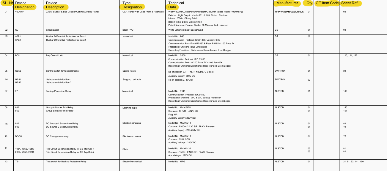
87B1 (Busbar Differential Protection for Bus-1): Located at 1759mm from the base [Sheet 03, Row: Upper Mid]. According to the Bill of Material [Sheet 10, Row 03], this is a GE Numerical Relay, Model 890, communicating via IEC61850. It acts as the absolute authority on faults occurring on Main Bus 1.
BCU (Bay Control Unit): Directly below at 1509mm. The BOM [Sheet 10, Row 04] identifies this as a GE C650. This is the command center for the operator and the SCADA system, housing the logic for breaker operations, isolator control, and alarms.
87B2 (Busbar Differential Protection for Bus-2): Mirroring Bus 1, this GE 890 relay sits at 1279mm, guarding Main Bus 2.
Figure 1 – General Arrangement of the 220kV Busbar and Bus Coupler Control and Relay Panel
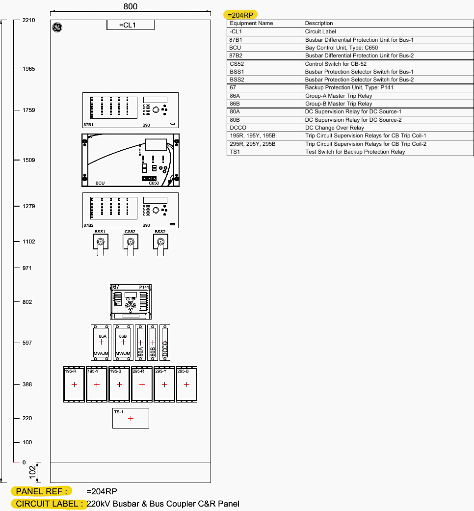
The Control Horizon: At 1102mm [Sheet 03, Row: Middle], at the optimal height for a human hand, sit the mechanical switches. BSS1 and BSS2 are lockable selector switches for Bus 1 and Bus 2 protection. Flanking them is CS52, the spring-return Control Switch (Trip-Neutral-Close) for the main circuit breaker.
67 (Backup Protection): Below the switches sits the Alstom P141 numerical relay. If primary systems fail, this Overcurrent and Earth Fault relay steps in.
Master Trip Relays: Below the 67 relay, we find the heavy-duty electromechanical latching relays: 86A and 86B (Model MVAJM25) [Sheet 03, Row: Lower Mid].
Trip Circuit Supervision: Below the master trips are six critical guardians: 195R, 195Y, 195B and 295R, 295Y, 295B. These are Alstom MVAXM31 static relays [Sheet 10, Row 10/11]. Because EHV breakers operate their R, Y, and B poles independently, each pole’s dual trip coils require independent health monitoring.
Figure 2 – BOM for the 220kV Busbar and Bus Coupler Control and Relay Panel
Chapter 2 – The Circulatory System
DC & AC Distribution
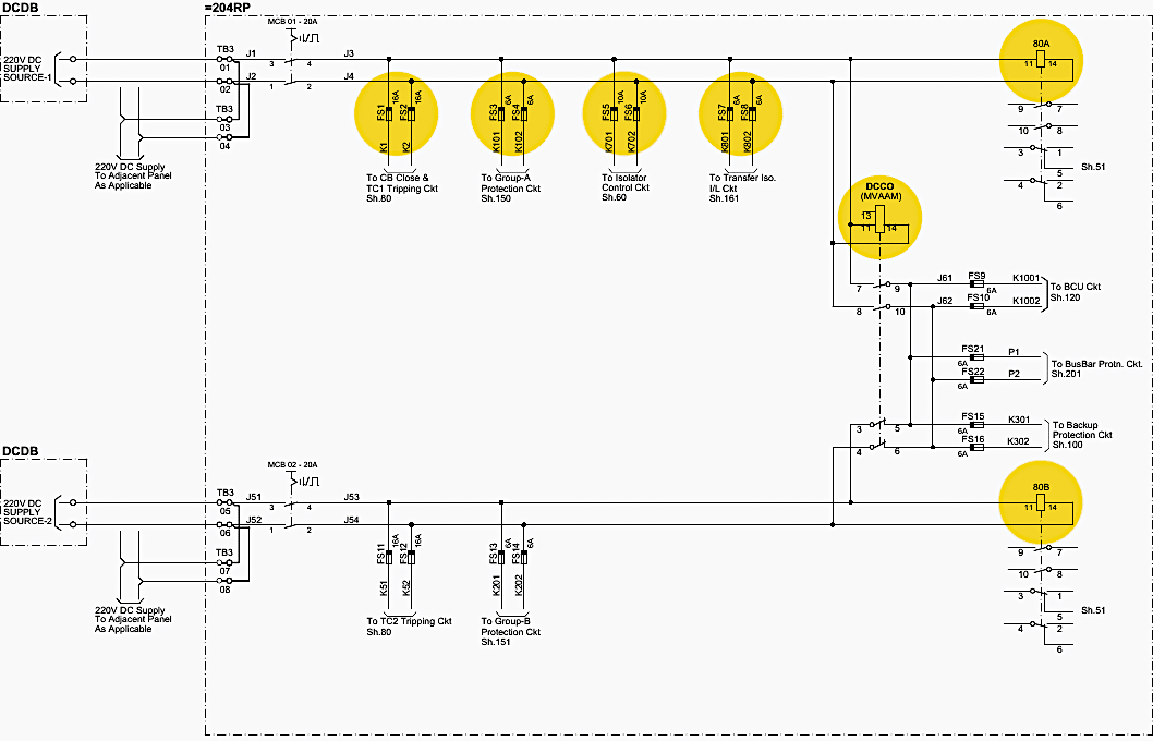
A relay without power is just a box of dormant silicon. The panel requires an unfailing power supply to operate its logic and drive its trip coils. We turn to Sheet 40: DC Distribution Circuit.
2.1 The DC Distribution Circuits
Reliability in transmission substations demands redundancy. At [Sheet 40, Row: Top, Column: Left], we see two independent 220V DC supplies entering the panel.
- Source-1 enters through MCB-01 (20A).
- Source-2 enters through MCB-02 (20A).
From the positive DC bus, the power branches out like tributaries through High Rupturing Capacity (HRC) fuses:
- FS1 & FS2 (16A): Feeds the Circuit Breaker (CB) Close and Trip Coil 1 (TC-1) circuits [Sheet 40, Row: Upper Mid, Column: Right].
- FS3 & FS4 (6A): Feeds the Group-A Protection logic.
- FS5 & FS6 (10A): Powers the robust mechanical drives of the Isolator Control circuits [Sheet 40, Row: Center, Column: Right].
- FS7 & FS8 (6A): Dedicates power specifically to the Transfer Isolator Interlock Circuit. (We will follow this specific tributary in great detail later).
Figure 3 – DC Distribution Circuits
2.2 The AC Auxiliary Circuit
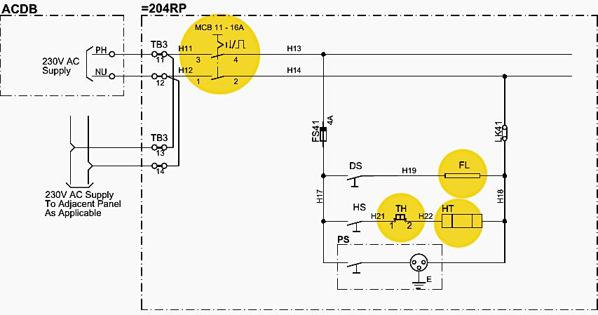
We flip to Sheet 42: AC Distribution Circuit. While DC drives the critical protection, 230V AC provides the environmental and maintenance life support. It enters via MCB-11 (16A) [Sheet 42, Row: Top, Column: Left].
This AC powers the internal panel illumination (CFL) via a door limit switch (DS). More importantly, it powers the Space Heater (HT, 60W) regulated by a Thermostat (TH, 30-110°C).
Substations experience extreme humidity and temperature shifts; the space heater prevents condensation from forming on the delicate printed circuit boards of the numerical relays, averting catastrophic short circuits.
Figure 4 – AC Auxiliary Circuit
Chapter 3 – The Senses
Current and Voltage Transformers
To protect the grid, the relays must “see” the power flowing through the 220kV conductors. They do this through Current Transformers (CTs) and Potential Transformers (PTs/IVTs). We analyze Sheets 21 through 26.
Related electrical guides & articles


Edvard Csanyi
Hi, I'm an electrical engineer, programmer and founder of EEP - Electrical Engineering Portal. I worked twelve years at Schneider Electric in the position of technical support for low- and medium-voltage projects and the design of busbar trunking systems.I'm highly specialized in the design of LV/MV switchgear and low-voltage, high-power busbar trunking (<6300A) in substations, commercial buildings and industry facilities. I'm also a professional in AutoCAD programming.
Profile: Edvard Csanyi