
Estimated Study Time: 7 minutes
Automatic transfer systems
Several common misconceptions regarding automatic transfer systems exist. Three of these are addressed here //
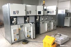
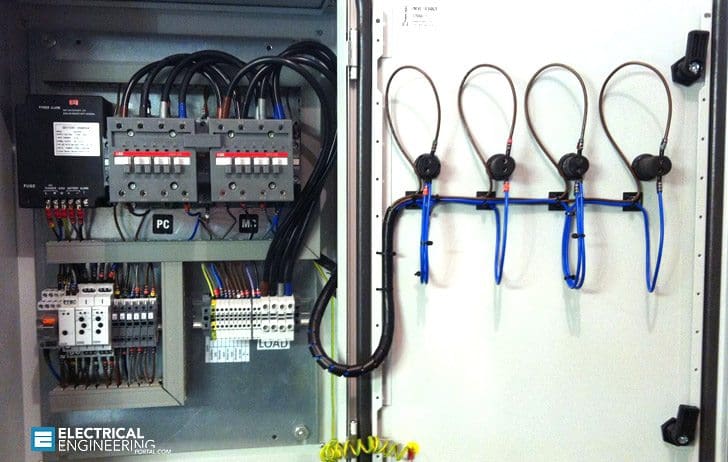 3 common misconceptions regarding automatic transfer systems (photo credit: bladespowergeneration.co.uk)
- I need a complex automatic transfer scheme at every voltage level
- AC Control Power for my automatic transfer PLC can be handled by the system UPS’s
- Since my automatic transfer system was tested in the factory, it doesn’t need field testing
Three most common ATS misconceptions //
Misconception #1
“I need a complex automatic transfer scheme at every voltage level”
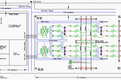
This may or may not be true, but in general if more than one automatic transfer scheme is present, the farther downstream it is, the less complex it has to be. For example, consider the system of Figure 1.
As shown in Figure 1 below, two automatic transfer systems exist, one at the medium voltage level and one at the low voltage level. The automatic transfer system at the low voltage level must be coordinated so that it does not transfer unless the reason for transfer is not addressed by a transfer on the system at the medium voltage level.
For example, should one of the utility sources fail, the medium voltage system will transfer to the other utility source.
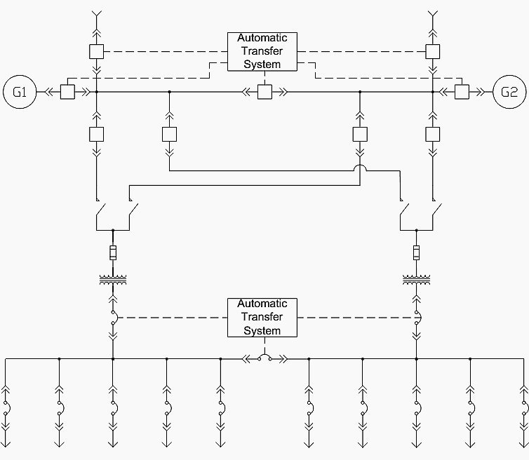
In that case, the low voltage transfer scheme should not transfer at all. However, should a fault occur on one of the medium voltage feeders, the low voltage system must transfer to restore power to the loads.
Further, in Figure 1 the generation is at the medium voltage level, so the low voltage automatic transfer system does not have to consider operation of the generators![]() . It is therefore less complex than the medium voltage automatic transfer system and will, in general, transfer less frequently.
. It is therefore less complex than the medium voltage automatic transfer system and will, in general, transfer less frequently.
Go back to ATS Misconceptions ↑
Misconception #2
“AC Control Power for my automatic transfer PLC can be handled by the system UPS’s”
On the surface, this is true. However, initial system start-up will require a power source other than the system UPS’s, which are devices downstream from the automatic transfer system. And, if a UPS is taken off-line for maintenance the availability of the control power can be compromised.
In reality, automatic transfer PLC’s have control power reliability requirements that are similar to microprocessor-based protective relays. Where those devices are used, the preferred power source is a DC battery system, and this is true for an automatic transfer PLC also.
Alternatively, a small UPS, supplied by a control transformer in the switchgear or switchboard, could be used. In either case, maintenance requirements apply to insure that the power is available when called upon.
In this case, a control power throw over is advisable, with one source being the switchgear or switchboard UPS, and the other being a system UPS or other reliable source.
AC control power for low voltage switchgear (or switchboards) used for automatic transfer is generally provided via a control power throw over supplied by control transformers in the equipment.
Energy to trip circuit breakers when no control power is available (i.e., after source failure but before standby generators are up and running) is provided via capacitive energy-storage devices. For medium voltage switchgear, the protective relays will have similar control power reliability requirements similar to those of the automatic transfer PLC, and DC batteries are typically used, but usually at the 48VDC or 125VDC level.
Many variations exist on switchgear, switchboard or PLC control power design, and this is an issue must be carefully considered to achieve the desired results.
Go back to ATS Misconceptions ↑
Misconception #3
“Since my automatic transfer system was tested in the factory, it doesn’t need field testing”
Like any other engineered system, factory testing for an automatic transfer system is no substitute for field testing. Field testing takes into account shipping damage and installation errors that may have occurred, as well as testing the system’s response to actual system conditions rather than simulated test conditions.
This is doubly important in the mission-critical environment, where reliable equipment operation is crucial.
Go back to ATS Misconceptions ↑
How an ATS Works with a Generator
Go back to ATS Misconceptions ↑
Reference // Critical Power Automatic Transfer Systems – Design and Application by Bill Brown, P.E., Jay Guditis, Square D Critical Power Competency Center (Schneider Electric)
Related electrical guides & articles


Edvard Csanyi
Hi, I'm an electrical engineer, programmer and founder of EEP - Electrical Engineering Portal. I worked twelve years at Schneider Electric in the position of technical support for low- and medium-voltage projects and the design of busbar trunking systems.I'm highly specialized in the design of LV/MV switchgear and low-voltage, high-power busbar trunking (<6300A) in substations, commercial buildings and industry facilities. I'm also a professional in AutoCAD programming.
Profile: Edvard Csanyi

Hi,
my suggestion is to use a dedicated microcontroller which can start quicker than PLC.
Additonaly in case when there are power sources like a transformer or generator with auto start (self detect) we don’t need UPS or DC supplier. To avoid a single point of failure, you need to build a redundant power supply for the controller or power it from the generator battery.
Regards,
Greg
thanks for all this informations