
Estimated Study Time: 9 minutes
PLC in adverse conditions
In certain applications, the operating environment may have extreme conditions that require special attention or otherwise can seriously damage PLCs. These adverse conditions include excessive noise and heat and nuisance line fluctuations. This article describes these conditions and provide measures to minimize their effects.
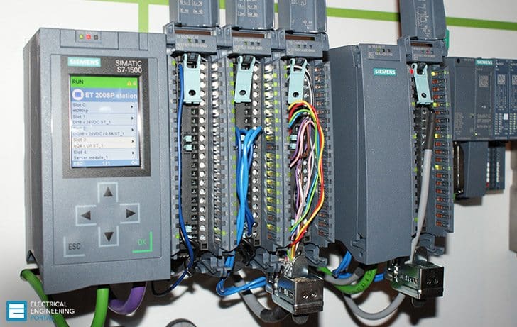 3 Conditions That Can Damage Your PLC (on photo: PLC SIMATIC S7-1500; credit: aei-automatizacion.com)
1. Excessive Noise
Electrical noise seldom damages PLC components, unless extremely high energy or high voltage levels are present. However, temporary malfunctions due to noise can result in hazardous machine operation in certain applications. Noise may be present only at certain times, or it may appear at widespread intervals. In some cases, it may exist continuously.
The first case is the most difficult to isolate and correct.
Noise usually enters a system through input, output, and power supply lines. Noise may also be coupled into these lines electrostatically through the capacitance between them and the noise signal carrier lines.
Devices that are potential noise generators include relays, solenoids, motors, and motor starters, especially when operated by hard contacts, such as push buttons and selector switches.

Analog I/O and transmitters are very susceptible to noise from electromechanical sources, causing jumps in counts during the reading of analog data. Therefore, motor starters, transformers, and other electromechanical devices should be kept away from analog signals, interfaces, and transmitters.
Although the design of solid-state controls provides a reasonable amount of noise immunity, the designer must still take special precautions to minimize noise, especially when the anticipated noise signal has characteristics similar to the desired control input signals.
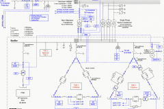
Sometimes, if the noise level situation is critical, all three-phase motor leads must be suppressed (see Figure 1 above). Figure 2 illustrates line-filtering configurations used for removing input power noise to a controller or transmitter.
Note 1 Keep line filters 12 inches or less from the controller. Minimize the line distance where noise can be introduced into the controller.
Note 2 To prevent ground loops, do not tie the common mode line metal case filters with other metal that is at ground potential. Doing so will reduce the filters’ effectiveness.
2. Excessive Heat
Programmable logic controllers can withstand temperatures ranging from 0 to 60°C. They are normally cooled by convection, meaning that a vertical column of air, drawn in an upward direction over the surface of the components, cools the PLC. To keep the temperature within limits, the cooling air at the base of the system must not exceed 60°C.
The manufacturer can provide spacing recommendations, which are based on typical conditions for most PLC applications. Typical conditions are as follows:
- 60% of the inputs are ON at any one time
- 30% of the outputs are ON at any one time
- the current supplied by all of the modules combined meets manufacturer-provided specifications
- the air temperature is around 40°C
Situations in which most of the I/O are ON at the same time and the air temperature is higher than 40°C are not typical. In these situations, spacing between components must be larger to provide better convection cooling.

If equipment inside or outside of the enclosure generates substantial amounts of heat and the I/O system is ON continuously, the enclosure should contain a fan that will reduce hot spots near the PLC system by providing good air circulation. The air being brought in by the fan should first pass through a filter to prevent dirt or other contaminants from entering the enclosure.
Dust obstructs the components’ heat dissipation capacity, as well as harms heat sinks when thermal conductivity to the surrounding air is lowered. In cases of extreme heat, the enclosure should be fitted with an air-conditioning unit or cooling control system that utilizes compressed air (see Figures 3 and 4).
Leaving enclosure doors open to cool off the system is not a good practice, since this allows conductive dust to enter the system.

There are methods available to calculate the temperature rise and heat dissipation requirements of an enclosure based on its size and equipment contents. Temperature rise is the temperature difference between the air inside an enclosure and the outside air temperature (ambient air temperature).
3.Excessive Line Voltage Variation
The power supply section of a PLC system can sustain line fluctuations and still allow the system to function within its operating margin. As long as the incoming voltage is adequate, the power supply provides all the logic voltages necessary to support the processor, memory, and I/O.
In applications that are subject to “soft” AC lines and unusual line variations, the first step towards a solution is to correct any possible feeder problem in the distribution system. If this correction does not solve the problem, then a constant voltage transformer can be used to prevent the system from shutting down too often (see Figure 5 below).

Constant voltage transformer //
The constant voltage transformer stabilizes the input voltage to the power supply and input field devices by compensating for voltage changes at the primary to maintain a steady voltage in the secondary.
Also, the user should connect the output devices in front of the constant voltage transformer, rather than behind it, so that the transformer is not providing power to the outputs. This arrangement will lessen the load supported by the transformer, allowing a smaller transformer to be used. The manufacturer can provide information regarding power rating requirements.
References //
- Programmable controllers: theory and implementation/L.A. Bryan, E.A. Bryan.—2nd edition, 1997
- Automating Manufacturing Systems with PLCs April 2005, version 4.7 / Hugh Jack
Related electrical guides & articles


Edvard Csanyi
Hi, I'm an electrical engineer, programmer and founder of EEP - Electrical Engineering Portal. I worked twelve years at Schneider Electric in the position of technical support for low- and medium-voltage projects and the design of busbar trunking systems.I'm highly specialized in the design of LV/MV switchgear and low-voltage, high-power busbar trunking (<6300A) in substations, commercial buildings and industry facilities. I'm also a professional in AutoCAD programming.
Profile: Edvard Csanyi

Dear Sir
Could you tell me what is the value of the noise it is specification for PLC Honeywell panel
Thanks
Huu Phu
I have faced failure in PLC card because of connectors physically becoming brittle or being damaged, failure in I/O channel signals, causing unwanted tripping.
Sir, Please guide maintenance procedures, recommended operating condition.
60% of the inputs are ON at any one time
30% of the outputs are ON at any one time
Is there any standart that refers the typical conditions?
hi sir i need some automation sample
Hello Mr. Edward,
I have Siemens PLC simatic S7 that is used to dicante oil to large tanks, but in the process of dicanting the fluid the PLC will display system error or the PLC just stop running. I normally turn the switch at the PLC module to stop and then turn turn is back to run position. Then the problem something will be cleared, but all in all, what is happening with this PLC causing unnecessary nuisance problems. The panel for the high voltage is separeted from the PLC section, i.e 480V to the motor, the only cable from from the VFD is the profibus cable connected to it for communication the the rest of the network. Would you please give me some insight as to what might be causing this problems. I like your article, it help me more when I read through it.
Thanks
Alex Elikana
Wago 750 XTR series -40 to 70C, 5kV surge protection, 5g vibration protection!
Thanks for all guys and for site admins
Hello sir
I want to know about Plc programing plz send me some data with pict for seek Plc
Regards
Usman mirza
Dear Sir,
Can you up load a standard single line diagram where 11kva (REB) line parallel with 5 gas generators and 2 diesel generators including Transformer, HT and LT Connection and PFI connection to distribution Bord(DB).
My dear Edvard,your subjects is very useful.
Be success always.
hello
your articles is very good and I use them in my work.
please write article about siemense s7 & pcs7 & profibus …
but please write them in pdf format
thank you very much
h.babadi
Hi guys ,
on the verge of this topic i would like to ask this
we have this cranes which unload Coal , Grab Ship Unloader,we are using ABB PLC in that we have 4 remote stations, suppose if welding works goes on near one of the stations, we switch off the whole PLC of the machine , even though the welding earth earth is connected near the Job site, The whole unloader is a gantry type it is having a copper bars connected to the track .
what i want to know is should we switch off the PLC for welding purposes? and what is the electrical stuff behind it ?
You Should first isolate the Earth Point of PLC/PLC Panel i.e Electronic Earthing & Electrical Earthing because u can not put both at same reference.Then Provide seperate Earthing Pit for Electronic Earthing,in there no earthing should be connected.So u can resolve ur problem by this.
Good morning,
it’s very interest tu see your article in my box.so thank you very much for all the team, and i hope to be with you.
kind regards