
Estimated Study Time: 16 minutes
Three-phase voltage transformations
Three-phase voltage transformations can be accomplished by using three phase transformers, which are single devices with all windings constructed on a single iron core. They also can be accomplished by using three single-phase transformers that are connected externally to form a three-phase bank.
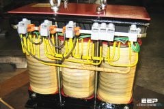
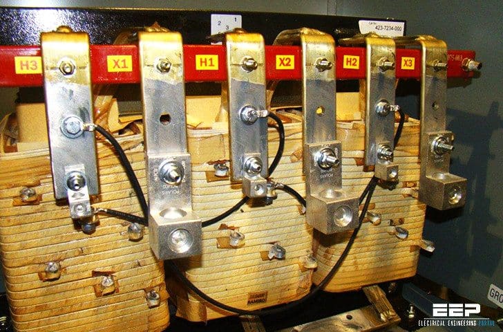 Easy understanding of 3-phase transformer connections - Delta–Delta, Wye–Wye, Delta–Wye and Wye–Delta (on photo: Jefferson Electric transformer)
While three-phase devices are usually the more cost-effective option, the single-phase option provides more versatility and can be attractive from a reliability and maintenance standpoint. If several identical transformers are needed at one location, the single-phase option can include the purchase of a spare unit to reduce outage time in the event of a failure.
This practice often is seen with critical autotransformer banks and generator step-up transformers because loss of the transformer for an extended period has very significant impacts.
The connections discussed in this article will be implemented using single-phase units.
Depending on how the windings are connected to the bushings, the polarities can be additive or subtractive.
The two most commonly used three-phase winding configurations are delta and wye, named after the Greek and English letter that each resembles. In a delta configuration, the three windings are connected end-to-end to form a closed path. A phase is connected to each corner of the delta.
Although delta windings are often operated ungrounded, a leg of the delta can be center tapped and grounded, or a corner of the delta can be grounded. In a wye configuration, one end of each of the three windings is connected to form a neutral. A phase is connected to the other end of the three windings. The neutral is usually grounded.
The following paragraphs describe three-phase transformers which utilize the delta and wye connections.
Next part of this article will discuss three-phase transformers using the open-delta and open-wye connections, where one of the single-phase transformers making up the three-phase bank is omitted. The leg of the transformer with the missing transformer is referred to as the phantom leg.
1. Delta–Delta transformer connection
Delta–delta transformers, as shown in Figure 1, often are used to supply loads that are primarily three phase but may have a small single-phase component.
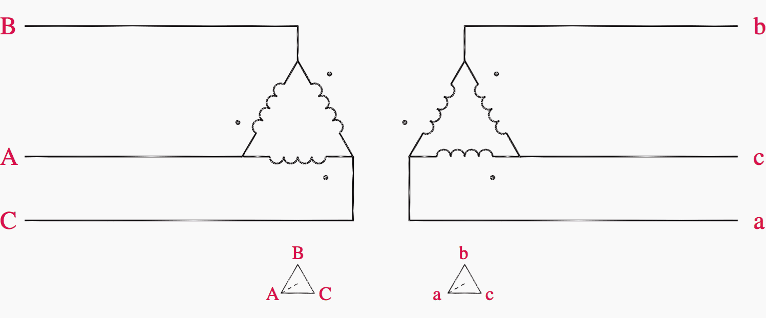
The three-phase load is typically motor load while the single-phase component is often lighting and low voltage power. The single-phase load can be fed by grounding a center tap on one of the legs of the delta secondary, then connecting the single-phase load between one of the phases on the grounded leg and this grounded neutral.
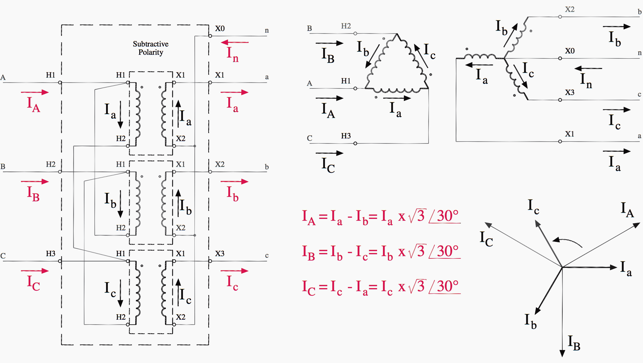
Figure 2 shows a delta–delta transformer connection.
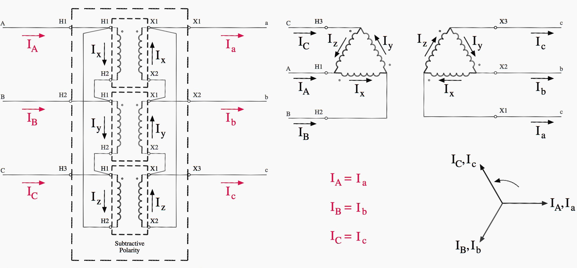
The connection diagram on the left shows how a delta–delta connection can be made, either with three single-phase transformers or with one three-phase transformer.
The dashed lines indicate the transformer outlines. The three single-phase transformer implementation can be seen by disregarding the outer dashed outline and the bushing labels shown at that outline, and concentrating on the three smaller (single-phase transformer) outlines.
The schematic diagram at the upper right is perhaps easier to analyze, as the delta connections can clearly be seen.
The phasor diagram at the lower right shows the geometric relationships between the high voltage circuit and low voltage circuit currents, and the equations at the bottom center show those relationships mathematically.
As the loading on a delta–delta transformer becomes unbalanced, high currents can circulate in the delta windings leading to a voltage imbalance. Balanced loading requires the selection of three transformers with equal voltage ratios and identical impedances.
Also, the amount of single-phase load should be kept low because the center-tapped transformer must supply most of the single-phase load. As the single-phase load is increased, the center-tapped transformer will increase its loading more than the other two transformers and will eventually overload.
If one of the single-phase transformers in the delta–delta bank fails, the bank can be operated with only two transformers forming an open delta configuration. The kVA rating of the bank is reduced, but three-phase power is still supplied to the load.
Watch Video – Delta-Delta transformer connection
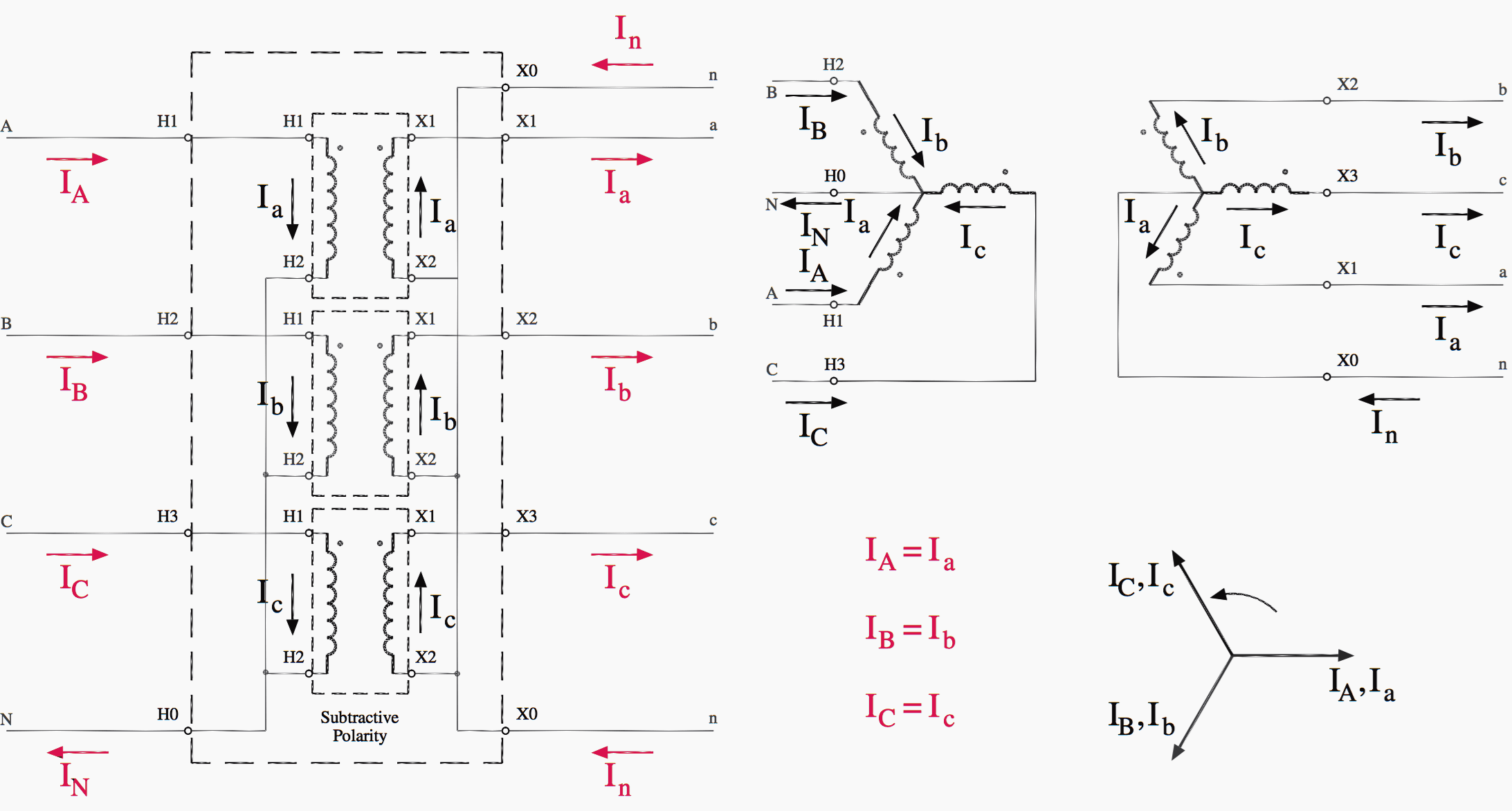
2. Wye–Wye transformer connection
Wye–wye transformers, as shown in Figure 3, can serve both three-phase and single-phase loads. The single-phase load should be distributed as evenly as possible between each of the three phases and neutral.

Figure 4 illustrates the wye–wye connection, either as three single-phase transformers or as a single three-phase unit. Both bushing labels and polarity dots are shown.
One problem inherent to wye–wye transformers is the propagation of third- harmonic currents and voltages. These harmonics can cause interference in nearby communication circuits as well as other assorted power quality problems.
Adding a third (tertiary) winding connected in delta alleviates many of the concerns mentioned.
Watch Video – Wye-Wye transformer connection
3. Delta–Wye transformer connection
The delta–wye connection is the most commonly used three-phase transformer connection. The wye-connected secondary allows single-phase load to be distributed among the three phases to neutral instead of being placed all on one winding as with a four-wire delta secondary.
If one of the single-phase transformers in the delta–wye bank fails, the entire bank becomes inoperative.
Also, since the delta–wye transformer introduces a 30° phase shift from primary to secondary as can be seen by the phasing symbols in Figure 5, it cannot be paralleled with delta–delta and wye–wye transformers that produce no phase shift.

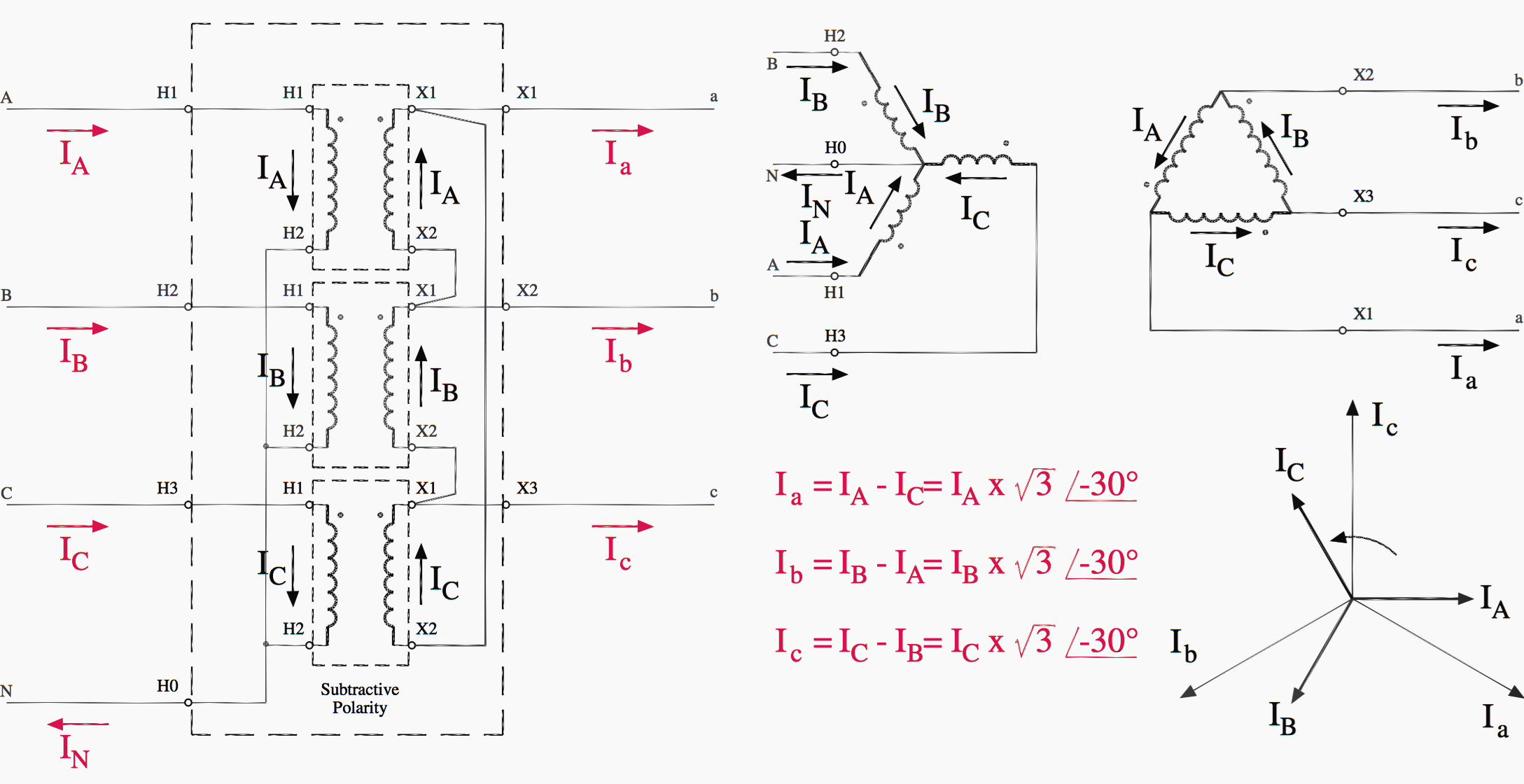
Figure 6 illustrates the delta–wye connection, either as three single-phase transformers or as a single three-phase unit. Both bushing labels and polarity dots are shown.
Analyzing the delta–wye transformer illustrates many important concepts regarding the operation of polyphase transformers. The analysis can be done on either a voltage or a current basis. Since voltage (potential difference or the subtraction of two phasor quantities) is rather abstract and difficult to visualize, current (or the flow of charge) will be used as the basis for analysis, since current is easy to conceptualize.
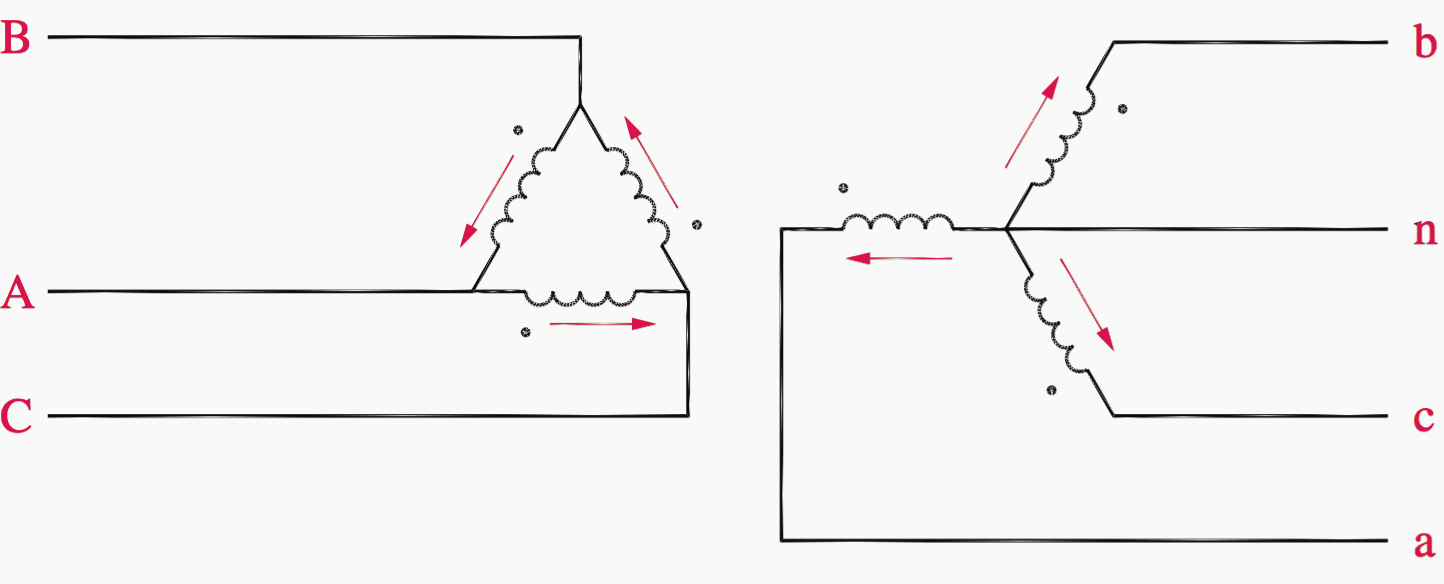
The currents owing in the windings of a delta–wye transformer are shown in Figure 7. Note that the arrows indicate instantaneous directions of the AC current and are consistent with the dot convention.
The analysis must begin in one of the two electric circuits, either the delta- connected high voltage circuit or the wye-connected low voltage circuit.
Since current is being used as the basis for analysis, the wye-connected circuit is selected as the starting point, since in a wye-connected circuit, the line currents (leaving the transformer) and the phase currents ( owing in the transformer windings) are equal. This relationship between line and phase currents simplifies the analysis.
The analysis starts by labeling all line and phase currents. This is shown in Figure 8.
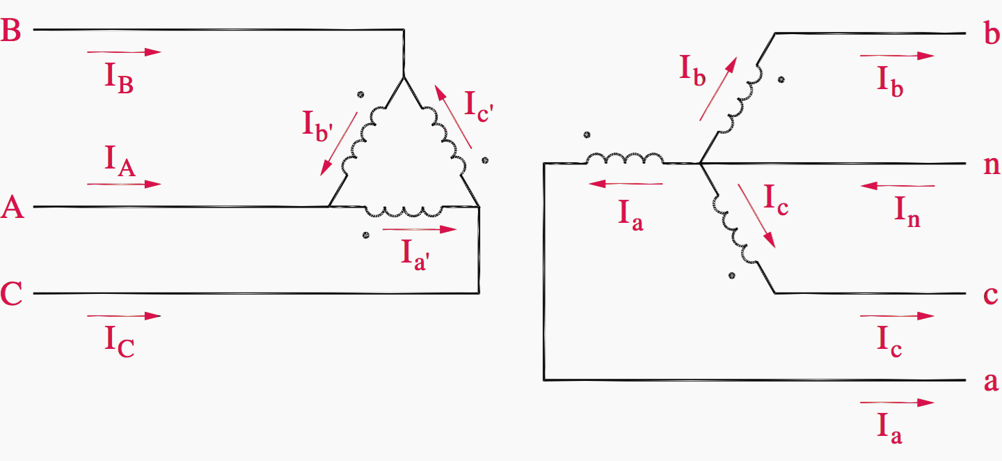
Note that lower-case subscripts indicate line currents in the low voltage circuit, and upper-case subscripts indicate line currents in the high voltage circuit. In the low voltage circuit, the phase currents are identical to the corresponding line currents, so they also are labeled Ia, Ib, and Ic. When the transformer windings are drawn, a particular high voltage winding corresponds to the low voltage winding drawn parallel to it.
The high voltage phase current corresponding to Ia is labeled Ia′ . The direction of Ia′ relative to that of Ia must honor the dot convention. The magnitude of Ia′ relative to Ia is the inverse of the transformer turns ratio “n”, or

When analyzing a transformer using per-unit, n = 1 so it becomes:
Ia′ = Ia
So,
Ia′ = Ia (per-unit)
Ib′ = Ib (per-unit)
Ic′ = Ic (per-unit)
(Eqs. 1)
Next, Kirchhoff’s current law can be applied to each node of the delta:
IA = Ia′− Ib′ = Ia − Ib
IB = Ib′− Ic′ = Ib − Ic
IC = Ic′− Ia′ = Ic − Ia
(Eqs. 2)
Equations above express the high voltage circuit line currents in terms of the low voltage circuit line currents. At this point, numerical values can be substituted for Ia, Ib, and Ic. Keeping in mind that Ia, Ib, and Ic represent a balanced set of phasors, arbitrary per-unit values are selected to represent a-b-c phase sequencing:

Substituting Eqs. 3 into Eqs. 2:

Comparing Ia to to IA, a √3 magnitude difference and a 30° angular difference are apparent.
IEEE Std. C57.12.00 defines the direction in which the phasor angles shall change from one electrical circuit to the other. In a standard delta–wye (or wye–delta) transformer, the positive-sequence currents and voltages on the high voltage side lead the positive-sequence currents and voltages on the low voltage side by 30°.
Note that the convention to determine a standard connection requires that the high voltage phasors lead the low voltage phasors by 30°. No reference is made to primary or secondary. The primary windings of a transformer are those windings to which voltage is applied. The secondary windings have an induced voltage impressed across them.
Usually, the primary windings are the high voltage windings, but this is not always the case. A good example of an exception is a generator step-up transformer.
Watch Video – Delta-Wye transformer connection
4. Wye–Delta transformer connection
The wye–delta transformer shown in Figure 9 is sometimes used to provide a neutral on a three-wire system but also can serve load from its secondary.
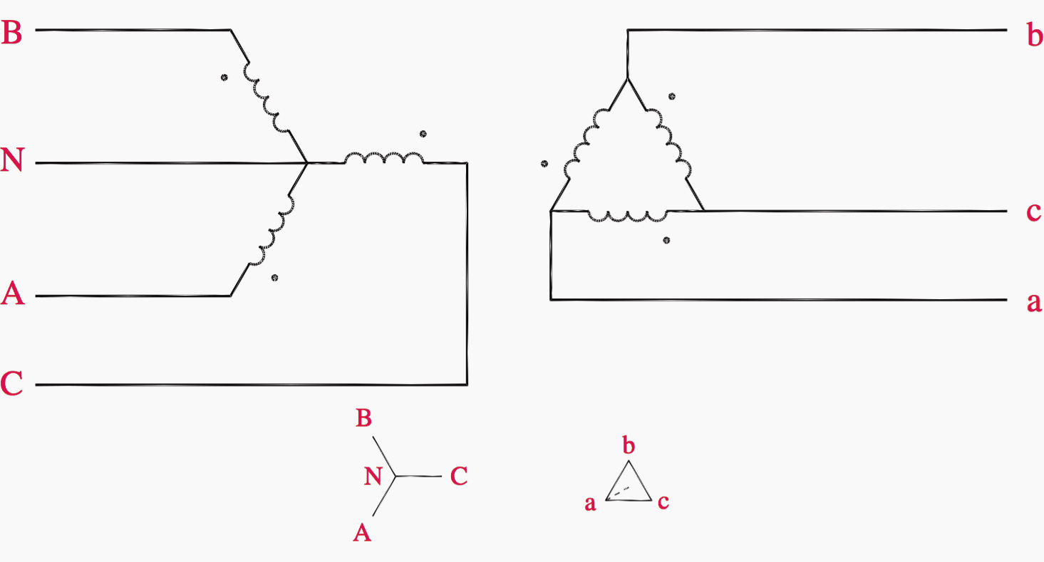
The primary wye windings are typically grounded. If the secondary is a four-wire delta, the fourth wire originating at a center tap on one of the legs of the delta is grounded.
Figure 10 illustrates the wye–delta connection, either as three single-phase transformers or as a single three-phase unit. Both bushing labels and polarity dots are shown.
Watch Video – Wye-Delta transformer connection
Will be continued…
Reference: Industrial power distribution by Ralph E.Fehr
Related electrical guides & articles


Edvard Csanyi
Hi, I'm an electrical engineer, programmer and founder of EEP - Electrical Engineering Portal. I worked twelve years at Schneider Electric in the position of technical support for low- and medium-voltage projects and the design of busbar trunking systems.I'm highly specialized in the design of LV/MV switchgear and low-voltage, high-power busbar trunking (<6300A) in substations, commercial buildings and industry facilities. I'm also a professional in AutoCAD programming.
Profile: Edvard Csanyi

Excellent article! Can you provide similar insights into the use of two Single phase CPTs in “Open Delta/Open Delta” formation with one of the CPTs having a center-tap to derive 240/120/208V on secondary?
I have three phase service ,240 high leg and I need 480 , I have three phase transformer it is a delta-wye transformer do I need to bond neautrAL to ground
Figure 10 has a mistake: left-half, lower-right (just above “subtractive polarity”) has connections X1 and X2 swapped
Amazing Article!!!
I’ve got a 3phase transformer which is missing the front cover with the label. It looks to be a 15 or 20 KVA. How can I determine its voltages? I put 230volts on the high side and got inconsistant readings on the low side…from 30volts up to 215volts. I was expecting it to read 115volts on the low side or less. Any suggestions?
Clean and simple explanation. Thanks!
Hi, just wanna ask how can we calculate Qloss in three phases?
How do I know Delta connection is correct?
Hi Edvard,
We have a 440 volts 3 phase supply line A, B, C that I do not know what configuration, Delta or Wye. It does not have a Neutral Line.
Our Load (3 phase motor with contactor controller) requires an Neutral line for the control circuit, which our power supply is not provided.
Can I connect three single phase transformer banks to form a Wye configuration at the power supply lines A, B, C and use its N line to be supplied to our load and provide Neutral Line?
How do I understand the transformer polarity on the delta connection?
In general, Wye will always have a neutral so i guess your supply network is a Delta.
With this the right solution that i foresee is a Delta-wye transformer that will provide you with ta neutral point.
In Figure 7 you said “Note that the arrows indicate instantaneous directions of the AC current and […]”, which is incorrect. All the three arrows for the phasor currents can’t indicate that the three currents are exiting from the secondary of the Tx at a given instant, otherwise that’d be a violation to Kirchhoff’s current law (at which point are the currents returning to the Tx? No, it’s not through the neutral, since no current flows through it at any instant for balanced systems.)
As a side note, the corresponding real instantaneous value of a phasor (i.e., the signal in the time domain), is only valid for t=0 sec or for any multiple of the period of the signals.
How would you draw it to make it understandable?
The point he was trying to make was the direction in relation to the polarity mark.
This is a great article. Thank you. When will it be continued?
-Bill J.
Sir,Please help me
Hi Engineers, I need help. Toronto Hydro required y/y transformer , for 27.6 KV prime , 480/277 second. less than 3000 MVA. Question. 1. Do I need to bring neutral conductor from HV switchgear? Second question. Do l need ground prime side neutral point.? Do I need ground secondary neutral point.? Thanks.
Very nice summary, Thanks!
How to downloads this file
I need a 3 phase distribution transformer (10 -15 kva) to provide 120 volts power to appliances. The power available is 3 phase, 240 volts line to neutral. What type of winding connection would be suitable Y-Y, D-Y, Y-D, or D-D?
I’d very much appreciate your expertise.
Thanks.
Allan Atsu
Ph: 306-693-0611
Cell: 306-690-2710
220v three phase is 110-110-220. Just use either of the two low legs. Why bother with a transformer?
i was interested if the 30 degree phase shift on delta wye transformers rights itself on reverse such as when used as a isolation transformer on a solar system
nice guruji. very clear and simple logic to understand the phase shift
great article Eng.Edvard. simple and useful, Thank you.
This a very big help to our lineman and also to our cadet engineers
This a very big help to our electrical engineering student…and also to us who are already practioner
Thanks Edvard for the great tutorial, it’s well written and easy to understand
Edvard: Re: A. Diallo’s request for circuit-breaker (or fuse) ratings.
You have of course dealt with general aspects of transformer protection (e.g. 7 Sep. 2016; 20 Feb 2016; 28 Nov. 2015), but you might consider giving some typical guidelines for protection settings such as:
* what multiple of full-load current for fuse or c/b on the secondary side?
* what multiple of F.L.C. if the protective device were in the primary circuit & would it protect adequately against an external fault in the secondary circuit?
* do we need to consider protecting against an internal fault? (Yes possibly, if the transformer is ever paralleled; a shorted turn can cause a significant voltage drop without shutting down the transformer, but that’s bad news for the other one.)
* and similar questions.
In response to his specific question, the manufacturer often provides recommended fuse ratings or breaker settings. For instance the ABB website, in their distribution transformer section has a ‘questions’ section. http://new.abb.com/products/transformers/distribution
D.R.
Why it became payment subscription instead of pdf. Whole world run behind the money??? Feeling dissatified
Very good
Hi Edward yes Daniel is right you helping many folk understand thing that sometimes are hard to grasp in school. Godspeed. I wonder if you can show how to set those lower voltage 9480 to 500 vac) tripping set point for breaker. Or if you have a link that you can point us.
Thank you again for your willingness to teach and educated tech through your website
You have developed one of the best electrical engineering website, you deserve it all, it is one of the website worthy to spend my learning time on.
Regards
Thank you Daniel, that’s very kind of you!