
Estimated Study Time: 15 minutes
Special cases of differential protection
Although the manufacturers of relays dedicated to differential protection impose the necessary CT secondary characteristics required for proper operation, it is useful, for understanding and avoiding errors, to possess minimum knowledge of this type of protection.
 Four Special Differential Protections And Their Respective CT Requirements (photo credit: elinstallatoren.se)
A differential protection monitors an area limited by CTs which measure incoming and outgoing currents. If the outgoing currents are not consistent with the incoming currents, this is normally because a fault has occurred in the protected area.
Now, let’s examine following protections with their respective CT requirements:
According to the type of protection and its use, relay manufacturers have had to apply a variety of principles varying in complexity in order to guarantee the stability of their relays against transient phenomena likely to cause nuisance tripping of this protection.
1. High impedance differential protection
This type of protection is normally used for protection of motors, generators, busbars as well as for “restricted earth fault” (REF) protection of transformers.
General
This type of protection is used to protect an area with the same voltage level. In healthy conditions, the input current i’e is identical to the output current i’s and thus the differential current i’d = 0 (see figure 1)
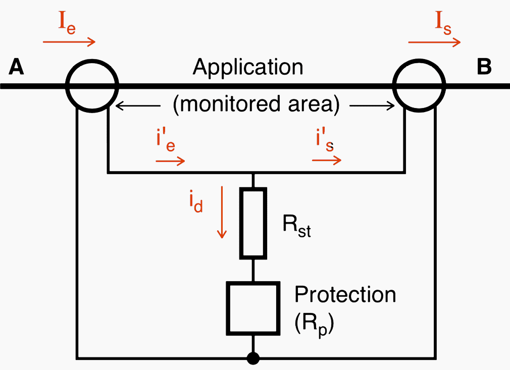
A high fault current can flow through the monitored area and cause CT saturation, hence the risk of nuisance tripping of the protection (non stability). The “stability” of the relay is obtained by connecting it in series with a “stabilising” resistance Rst.
This results in (1): (Rst + Rp) ≥ (Rct + 2 RL) × Issc / Ir
where:
- Issc = maximum through current observed at the CT secondary,
- Ir = relay secondary setting current.
- Rst may vary between a few ohms and a few hundred ohms (exceptionally it may be greater than 1000 ohms).
For the relay to operate properly at Ir if a fault occurs in the area, the knee point voltage Vk must be greater than:
2 × (Rst + Rp + Rct + 2 RL) × Ir .
As a rule Rct + 2 × RL are negligible compared with Rst + Rp thus (2):
Vk ≥ 2 × Ir × (Rst + Rp)
By combining the equations (1) and (2) we find (3):
Vk ≥ 2 × Issc × (Rct + 2 × RL)
The result of these observations is that the CTs are optimized if Rct and Vk are as low as possible and if the through current (seen from the CT secondary, i.e. Iscc) is defined without excess.
Whatever the application where the high impedance differential is used, all the CTs must have:
- The same ratio,
- The same magnetising curve (same minimum Vk),
- The same maximum Rct,
- And comply with expression (3). For Vk, since the relevant CTs are not at the same distance from the relay, take the maximum RL.
For this protection, a maximum value of the magnetizing current Io must also be defined at Vk / 2 according to the required sensitivity.
For the relay to detect a current Ir, a voltage Vs = Vk / 2 must be developed at the terminals of the parallel-connected CTs. For this purpose, the minimum primary current Irms really detected by the relay will be:
Irms = n × (Ir + ρ × Io)
where:
- n = CT ratio and
- ρ = number of parallel-connected CTs (there may be many of them on a busbar protection!)
Application to the “motor” differential protection
The maximum through current for which the motor must remain insensitive is in this case the motor starting current:
Issc = Ist (seen at the secondary).
If you do not know this current Ist, you know that:
Ist < 7 × In motor
Application to the “generator” differential protection
The maximum through current is in this case the short-circuit current supplied by this generator only. If you know the generator subtransient reactance X’’ %, the following will be taken:
Issc = In × 100 / X”
If this value is not known, X’’ % = 15 will be taken.
Note – The peak voltage at the CT secondary must be calculated using:
Issc maxi = I”generator + Isc network
Application to the “busbar” differential protection
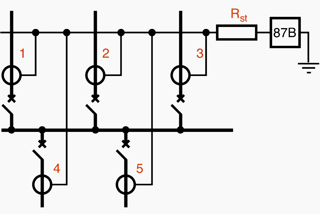
In this case, the through current is equal to switchboard Isc:
Issc = switchboard Isc seen from the CT secondary
Application to the “restricted earth fault” differential protection of transformers (REF)
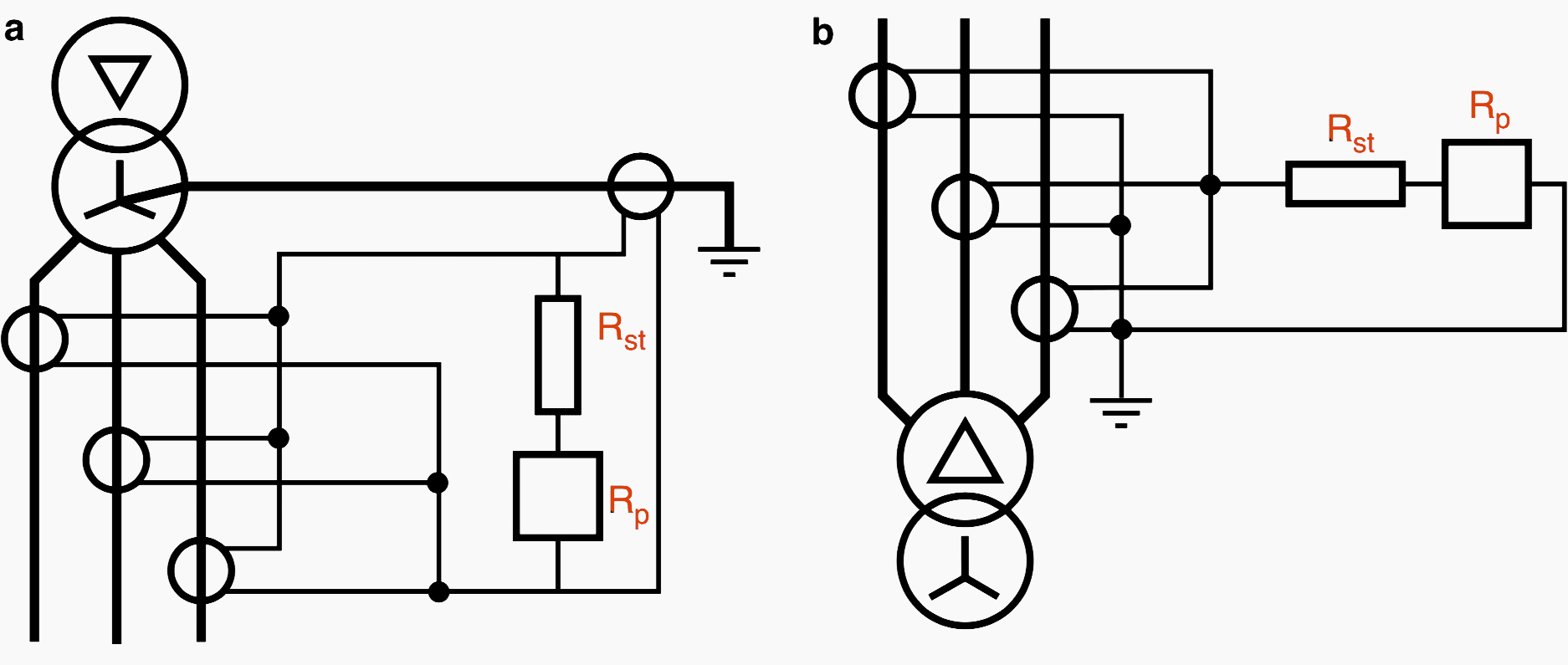
In the case of figure 3a , this protection detects the insulation faults at the transformer secondary windings and up to the CTs located downstream.
In this case also, we shall calculate Rst and Vk based on the maximum through current in the CTs for a fault outside the protected area. As a first approximation, we can say that this current is less than the current limited by the transformer
impedance, i.e.
Ithrough = Psct / (Un × √3)
where Psct = Pn × 100 / Zsc (transformer short-circuit power)
If we know the upstream short-circuit power (Pu), a more accurate value can be calculated replacing:
Psct with (Psct × Pu) / (Psct + Pu)
The through fault current must then be converted into Issc seen at the CT secondary.
2. Line or cable differential protection with pilot wires
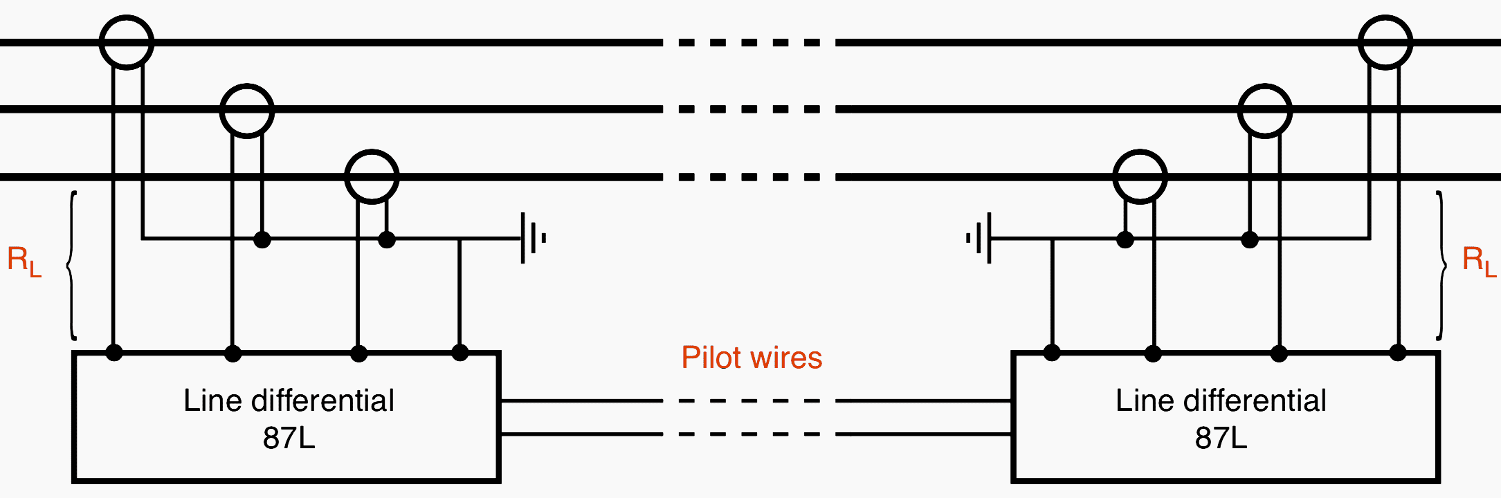
A relay of this type is installed at each end of the cable or the line. On the pilot wires, each relay reproduces a voltage which is the image of the sum:
a×I1 + b×I2 + c×I3 + d×Ih
If the two voltages are different, both relays trip.
In this case also, class X CTs are required, and each manufacturer gives an empirical formula for the minimum knee point voltage Vk.
An example of the minimum knee point voltage required:
Vk mini = 0,5 ×N × kt × In × (Rct + X × RL)
where N, kt and X are constants associated with the relay response time, its sensitivity and its type of connection.
Another example:
Vk mini = 50/In + If × (Rct + 2 × RL)
where
- In is the CT nominal secondary current (1 or 5 A),
- If is the through short-circuit current, seen at the CT secondary.
However, their magnetizing curves and Rct do not need to be identical.
3. Percentage biased differential protection for transformers
The term “percentage differential” stems from the fact that the operating threshold increases with the through current.
Simple comparison of the currents in each upstream phase with the currents in the same downstream phases is not suitable for transformer differential protection.
This is because:
- The upstream and downstream currents of a power transformer do not have the same amplitude or the same phase angle,
- When the transformer is energised, its magnetising current is only seen upstream,
- The presence of an earthing generator in the protected area (e.g. earthing the transformer neutral) can trip the protection, while the fault is, for example, located on a downstream feeder.
Precautions to be taken to solve these problems:
The aim is to ensure that the relay sees upstream and downstream currents of the same amplitude and in phase during normal operating conditions. This can be achieved by intelligent choice of CT ratio and connections.
Furthermore, it must be noted that all the “transformer differential” relays are immunized to the 2nd order harmonic blocking their operation when the transformer is energised.
CT voltage Vk
In 99 % of cases, a class X is requested. The minimum knee point voltage is imposed and depends on the resistance of the secondary winding “Rct” of the CT and of its real load Rr. More complex specifications are sometimes mentioned, which include the X/R ratio of the network or the magnetising current of the power transformer.
However, faced with the problems that users have in obtaining all these parameters, relay suppliers sometimes provide simplified empirical formulas which lead to a slight oversizing.
Examples of minimum knee point voltage imposed for the Schneider Electric’s Sepam protection relay:
Vk mini = A × Ib (Rct + 2 × RL)
where:
- 2 × RL = total resistance of the secondary wiring,
- Rct = CT secondary winding resistance,
- Ib = power transformer nominal current seen at the CT secondary,
- A = constant depending on transformer power
Some suppliers take into account the through current, for example:
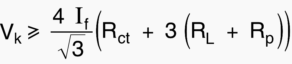
on the star side of the power transformer,
and Vk ≥ 4 × If × (Rct + 2×RL + Rp) on the delta side of the power transformer. The through current will be defined in the same way as for the restricted earth fault protection.
NOTE: Use of matching CTs leads to different expressions of the knee point voltage for the main CTs which must take into account the extra load that they represent.
To conclude, the stability of this protection is ensured by:
- The threshold which increases with the through current (restraint system),
- The right choice of CT knee point voltage Vk,
- A system ensuring immunity to 2nd order harmonics generated by inrush currents,
- The most sophisticated relays are also immune to 5th order harmonics which occur during power transformer overexcitation (saturation).
4. Low impedance differential protection
This protection is used for busbar differential protection. It is very costly and space-consuming, as it requires a large number of modules and matching CTs which need one or more cubicles according to switchboard size (see figure 5).
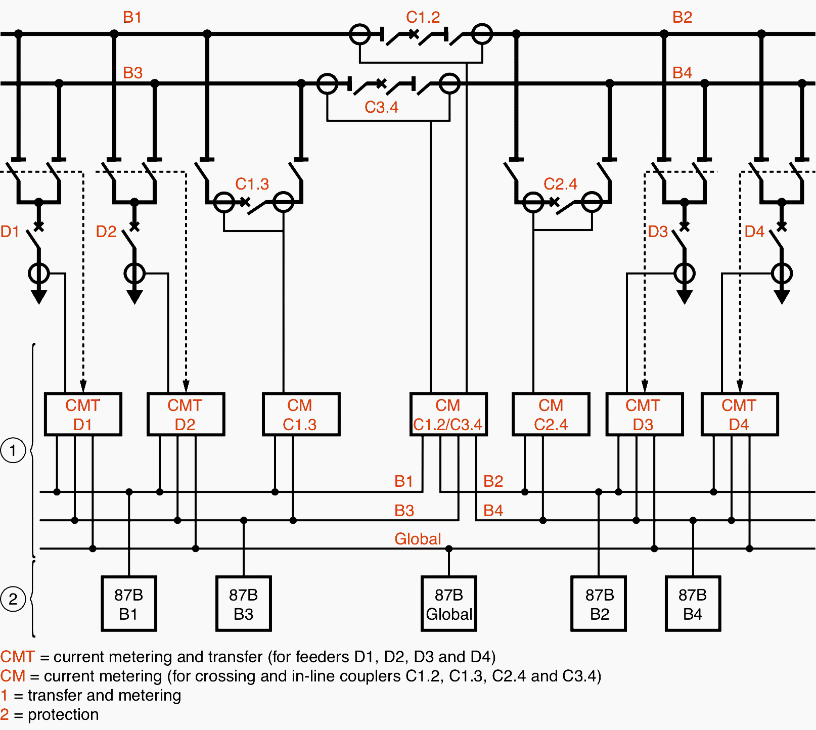
In the case of a double busbar switchboard, the protection must be continually “informed” on the position of the transfer switches in order to direct the currents of each feeder and incomer to the relay associated with monitoring of the busbar on which this feeder or incomer is connected.
However, as saturation can be tolerated, knee point voltage requirements are less severe than for high impedance differential protection.
Reference // Current transformers: how to specify them by P. Fonti (Schneider Electric)
Related electrical guides & articles


Edvard Csanyi
Hi, I'm an electrical engineer, programmer and founder of EEP - Electrical Engineering Portal. I worked twelve years at Schneider Electric in the position of technical support for low- and medium-voltage projects and the design of busbar trunking systems.I'm highly specialized in the design of LV/MV switchgear and low-voltage, high-power busbar trunking (<6300A) in substations, commercial buildings and industry facilities. I'm also a professional in AutoCAD programming.
Profile: Edvard Csanyi

Sir, in case of important protections in / for substation, 1 more may please be added for DC control supply circuitry i.e. alarm for D. C. Earth Leakage. Protection to prevent nuisance operation of circuit breakers or any other components in generating stations.
If in case for line differential protection, I have two different CT (Ratio,etc is different) at both ends. How can we utilize this protection. In simple way, why it is must to provide matching type CT including all parameters at both sides. Please provide me response in such a way that using some calculation for my better understanding
Dear Sir
In IEC 60038 why gap between 230KV to 245KV as below in band 4 to 5
band 1 – A.C. systems 100 V to 1000 V
band 2 – A.C and D.C traction systems
band 3 – A.C. systems above 1 kV to 35 kV
band 4 – A.C. systems above 35 kV to 230 kV
band 5 – A.C. systems above 245 kV
Hi
In case of a fault on line between a transformer and their breaker
Who will initiate the trip first the 51 protection or 87 T.
Thanks in advance.
The primary protection which is 87. 51 is the back up protection, whenever the primary protection fails to operate then the back up protection will operate.