
Distribution Feeder Systems
Let’s take a look at the four most common distribution feeder systems applied nowadays. There are few other variations, but we will stick to the basic ones. It’s very important to understand why and where each of distribution feeder systems (topologies) are used, because whatever you do (design of secondary substations, performing testing of secondary switchgears or transformers or planning etc.) this would be the very first thing to know.
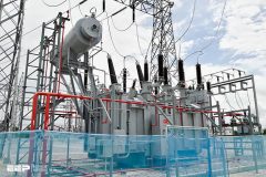
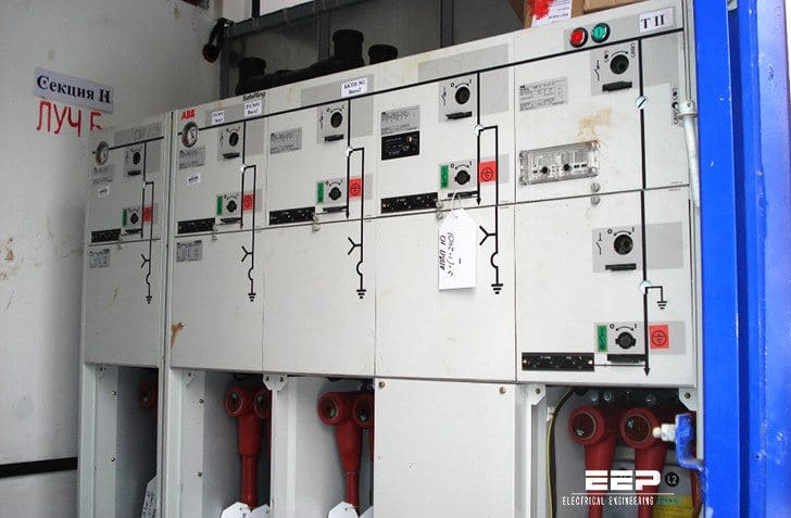 4 Main Types Of Distribution Feeder Systems To Recognize (on photo: ABB's ring main unit; credit: transmar.ru)
So, these are the distribution feeder systems we’ll speak about //
1. Radial
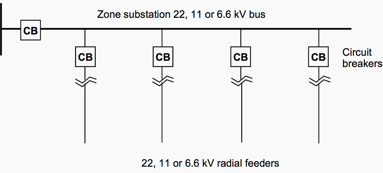
Many distribution systems operate using a radial feeder system. A typical radial feeder system is shown schematically in Figure 2. Radial feeders are the simplest and least expensive, both to construct and for their protection system.
This advantage however is offset by the difficulty of maintaining supply in the event of a fault occurring in the feeder.
A fault would result in the loss of supply to a number of customers until the fault is located and cleared. The next level of reliability is given by a ‘parallel feeder’ system.
Go back to Distribution Feeder Systems ↑
2. Parallel feeders
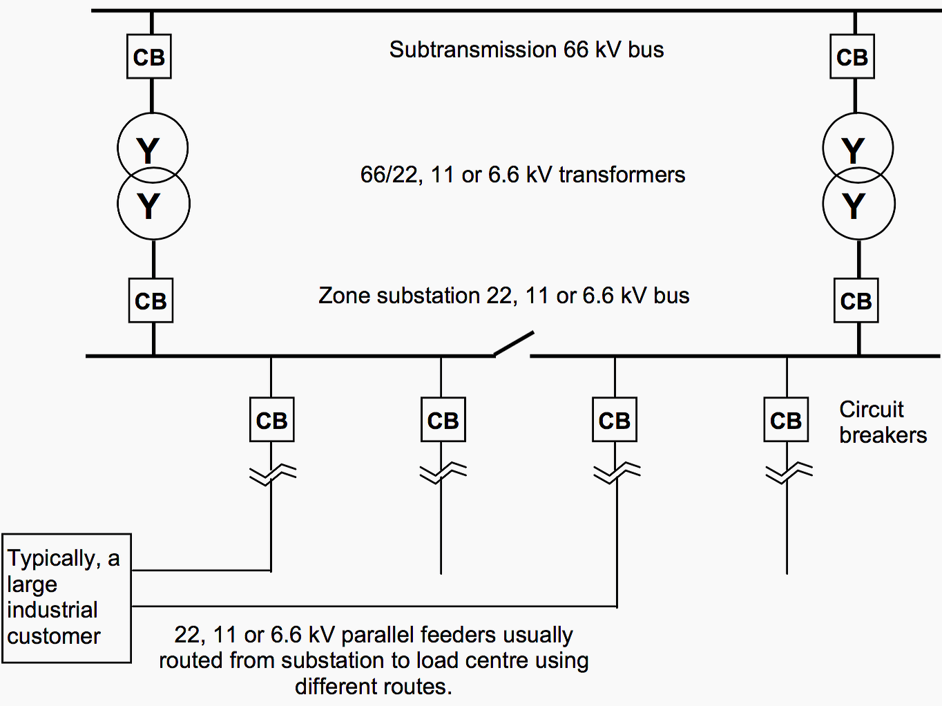
A greater level of reliability at a higher cost is achieved with a parallel feeder. A typical parallel feeder system is shown schematically in Figure 3.
To improve the reliability factor it may be possible to have the separate sets of cables follow different routes. In this case the capital cost is double that of a radial feeder but there is a greater reliability factor for the line. This may be justified if the load is higher, more customers are being supplied, or there are loads such as hospitals which require high levels of reliability.
Parallel feeders are more common in urban areas or for feeders to large single customers, where load shedding in an emergency may be possible.
Go back to Distribution Feeder Systems ↑
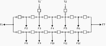
3. Ring main
A similar level of system reliability to that of the parallel arrangement can be achieved by using ring main feeders. This usually results from the growth of load supplied by a parallel feeder where the cabling has been installed along different routes. These are most common in urban and industrial environments.
Whilst the start and finish ends of the ring are at the same location, power is delivered by both pathways of the ring into substations located around the ring.
In typical urban / suburban ring main arrangements, the open ring is operated manually and loss of supply restored by manual switching.
Current practice is to use distribution automation, where operation and supply restoration in the feeder rings is done automatically by centrally controlled supervisory systems.
This gives the advantages of ring main systems as line voltage drops are reduced at the various load substations there is a ‘firm’ supply (i.e. an alternative path is available if the primary one fails) to each load substation.
Go back to Distribution Feeder Systems ↑
4. Meshed systems
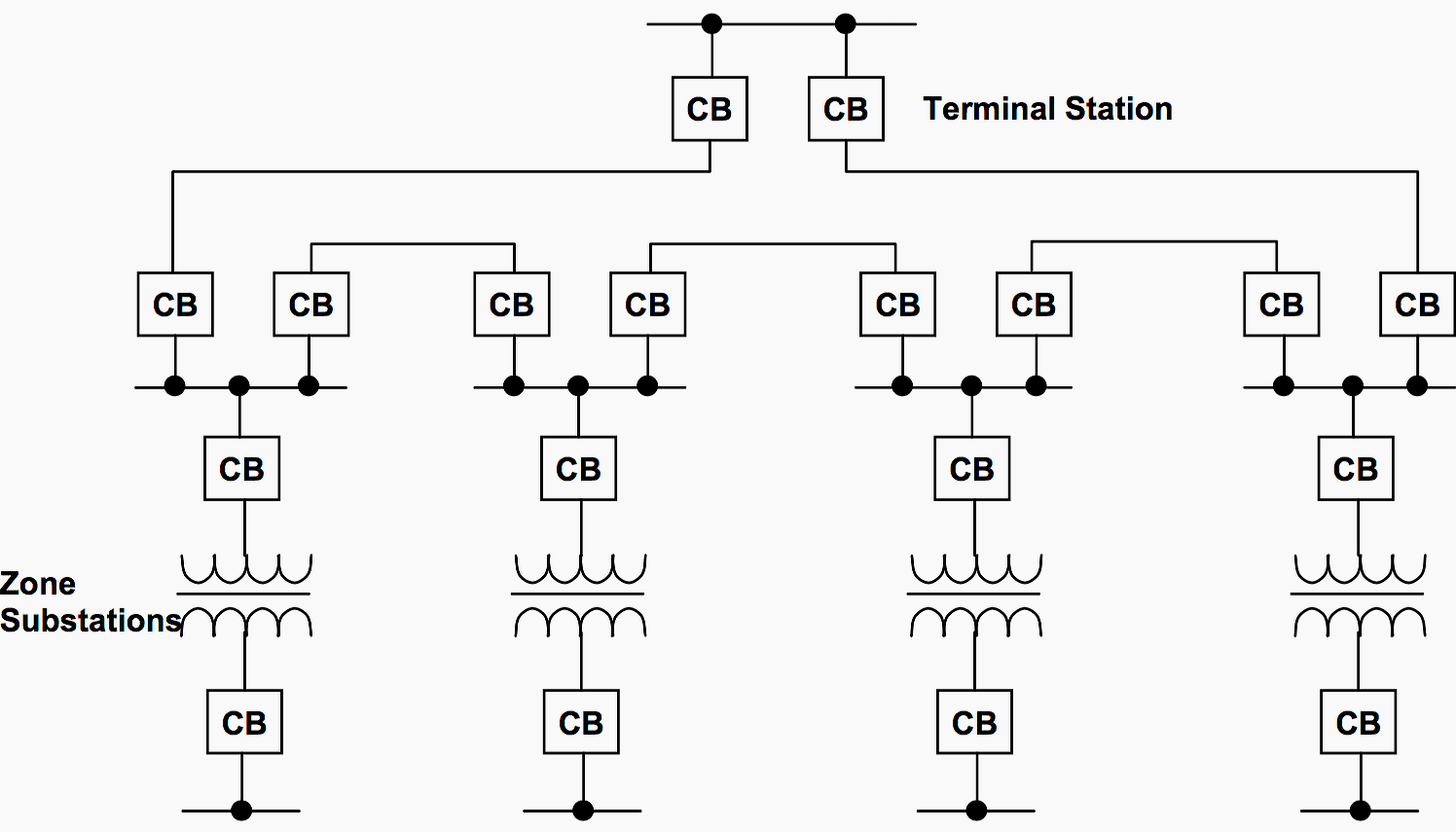
In transmission and sub-transmission systems, usually parallel, ring or interconnected (mesh) systems are used. This ensures that alternative supply can be made to customers in the event of failure of a transmission line or element.
The general rule is that where large loads or numbers of customers are involved, then some form of standby, in the form of deliberate redundancy, is built into the network design, through the use of parallel, meshed or ring type feeders.
Only in outer rural areas would one consider using only radial supply at a sub-transmission level. On the other hand, simple radial supply is almost universally used for low voltage (400V) feeders, even in urban areas, because they supply relatively few customers.
Go back to Distribution Feeder Systems ↑
Medium voltage switchgear NXAIR
NXAIR – The medium voltage air-insulated switchgear from Siemens, type-tested for indoor installation according to IEC 62271-200.
Reference // Design guide for overhead distribution systems – Chisholm Institute of TAFE, Electrical, Electronics Engineering Department


the parallel system also include parallel in the transformer not only parallel in the C.B
Very important and informative.
Dears
we have a residence housing project which supplied from 33kV switch gear. in case of electricity shortage we installed backup set of generators ,synchronized and we want to feed the project by stepping up DG voltage from 400 V to 33kV volt . this will be through 0.4/33kV transformer and 33kV ATS panels. my question was which vector group should be the step up transformer if we know the 33kV line is 3 cables (RST) and the DG output is 4 wire (RST-N).
great read
Sir there is a need of Pdf so we can take advantage by offline.
Great efforts Eng Edvard 👍
Thank you
Great job on your website
This site useful to me and I wants to connect this site it’s very useful☺
Hello Mr o Ms.
My name is Daniel Castañeda Galva. I´m from Mexico. I´m studied electrical mechanic engineer.
I´m desinging electrical installition for hospital.
Can you have any electrical software?
Thank you!!
Thank you Edvard for your generosity. The info here is great
Thank you Jackie.
Great job on your website
Good day. Please I’m working on a project and I’ve been wondering, can a single electricity distribution pole have any amount of distribution feeders (like 10) or is there a particular amount? Thanks.
I need to learn more about the designing procedure of variouscontrol circuits and programming in Siemens plc. Can u guide me.
I feel interested in reading this. I want to know more. This helps in learning good. Thank u so much.