
Estimated Study Time: 13 minutes
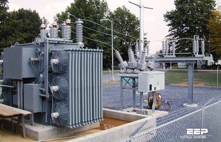
Oil Transformer protection
The power transformer protection is realized with two different kinds of devices, namely the devices that are measuring the electrical quantities affecting the transformer through instrument transformers and the devices that are indicating the status of the physical quantities at the transformer itself.
An example of the former could be current-based differential protection and of the latter oil temperature monitoring.
Protection Devices //
The following discusses protection devices typically delivered as a part of the power transformer delivery.
The power transformer protection as a whole and the utilization of the below presented protection devices are not discussed here.
1. Buchholz (Gas) Relay
The Buchholz protection is a mechanical fault detector for electrical faults in oil-immersed transformers. The Buchholz (gas) relay is placed in the piping between the transformer main tank and the oil conservator. The conservator pipe must be inclined slightly for reliable operation.
Often there is a bypass pipe that makes it possible to take the Buchholz relay out of service.

The Buchholz protection is a fast and sensitive fault detector. It works independent of the number of transformer windings, tap changer position and instrument transformers. If the tap changer is of the on-tank (container) type, having its own oil enclosure with oil conservator, there is a dedicated Buchholz relay for the tap changer.
A typical Buchholz protection comprises a pivoted float (F) and a pivoted vane (V) as shown in Figure 1. The float carries one mercury switch and the vane also carries another mercury switch. Normally, the casing is filled with oil and the mercury switches are open.

When minor fault occurs…
Here is assumed that a minor fault occurs within the transformer. Gases produced by minor faults rise from the fault location to the top of the transformer. Then the gas bubbles pass up the piping to the conservator. The gas bubbles will be tapped in the casing of the Buchholz protection.
This means that the gas replaces the oil in the casing. As the oil level falls, the float (F) will follow and the mercury switch tilts and closes an alarm circuit.
When major fault occurs…
It is also assumed that a major fault, either to earth of between phases or windings, occurs within the transformer. Such faults rapidly produce large volumes of gas (more than 50 cm3/(kWs) and oil vapor which cannot escape.
They therefore produce a steep buildup of pressure and displace oil. This sets up a rapid flow from the transformer towards the conservator. The vane (V) responds to high oil and gas flow in the pipe to the conservator. In this case, the mercury switch closes a trip circuit. The operating time of the trip contact depends on the location of the fault and the magnitude of the fault current.
The gas accumulator relay also provides a long-term accumulation of gasses associated with overheating of various parts of the transformer conductor and insulation systems. This will detect fault sources in their early stages and prevent significant damage.

When the transformer is first put into service, the air trapped in the windings may give unnecessary alarm signals. It is customary to remove the air in the power transformers by vacuum treatment during the filling of the transformer tank with oil.
The gas accumulated without this treatment will, of course, be air, which can be confirmed by seeing that it is not inflammable.
Other technical articles related to Buchholz relay //
2. Pressure Relay
Many power transformers with an on-tank-type tap changer have a pressure protection for the separate tap changer oil compartment. This protection detects a sudden rate-of-increase of pressure inside the tap changer oil enclosure.
Figure 3 shows the principle of a pressure relay.

When the pressure in front of the piston exceeds the counter force of the spring, the piston will move operating the switching contacts. The micro switch inside the switching unit is hermetically sealed and pressurized with nitrogen gas.
The simplest form of pressure relief device is the widely used frangible disk. The surge of oil caused by a heavy internal fault bursts the disk and allows the oil to discharge rapidly. Relieving and limiting the pressure rise prevent explosive rupture of the tank and consequent fire.
Also, if used, the separate tap changer oil enclosure can be fitted with a pressure relief device.

The pressure relief device can be fitted with contact unit(s) to provide a signal for circuit breaker(s) tripping circuits.

A drawback of the frangible disk is that the oil remaining in the tank is left exposed to the atmosphere after a rupture. This is avoided in a more effective device, the pressure relief valve, which opens to allow the discharge of oil if the pressure exceeds the pre-adjusted limit.
If the abnormal pressure is relatively high, this spring-controlled valve can operate within a few milliseconds and provide fast tripping when suitable contacts are fitted. The valve closes automatically as the internal pressure falls below a critical level.
3. Oil Level Monitor Device
Transformers with oil conservator(s) (expansion tank) often have an oil level monitor. Usually, the monitor has two contacts for alarm. One contact is for maximum oil level alarm and the other contact is for minimum oil level alarm.

The top-oil thermometer has a liquid thermometer bulb in a pocket at the top of the transformer. The thermometer measures the top-oil temperature of the transformer. The top-oil thermometer can have one to four contacts, which sequentially close at successively higher temperature.
The figure below shows the construction of a capillary-type top-oil thermometer, where the bulb is situated in a “pocket” surrounded by oil on top of the transformer. The bulb is connected to the measuring bellow inside the main unit via a capillary tube. The bellow moves the indicator through mechanical linkages, resulting in the operation of the contacts at set temperatures.

The top-oil temperature may be considerably lower than the winding temperature, especially shortly after a sudden load increase. This means that the top-oil thermometer is not an effective overheating protection.
However, where the policy towards transformers’ loss of life permits, tripping on top-oil temperature may be satisfactory. This has the added advantage of directly monitoring the oil temperature to ensure that it does not reach the flash temperature.
4. Winding Thermometer
The winding thermometer, shown in the figure below, responds to both the top-oil temperature and the heating effect of the load current.

The winding thermometer creates an image of the hottest part of the winding. The top-oil temperature is measured with a similar method as introduced earlier. The measurement is further expanded with a current signal proportional to the loading current in the winding.
This current signal is taken from a current transformer located inside the bushing of that particular winding. This current is lead to a resistor element in the main unit. This resistor heats up, and as a result of the current flowing through it, it will in its turn heat up the measurement bellow, resulting in an increased indicator movement.

The temperature bias is proportional to the resistance of the electric heating (resistor) element.
The result of the heat run provides data to adjust the resistance and thereby the temperature bias. The bias should correspond to the difference between the hot-spot temperature and the top-oil temperature. The time constant of the heating of the pocket should match the time constant of the heating of the winding.
The temperature sensor then measures a temperature that is equal to the winding temperature if the bias is equal to the temperature difference and the time constants are equal.
With four contacts fitted, the two lowest levels are commonly used to start fans or pumps for forced cooling, the third level to initiate an alarm and the fourth step to trip load breakers or de-energize the transformer or both.
In case a power transformer is fitted with top-oil thermometer and winding thermometer, the latter one normally takes care of the forced cooling control.
Reference // Distribution Automation Handbook – ABB
Related electrical guides & articles


Edvard Csanyi
Hi, I'm an electrical engineer, programmer and founder of EEP - Electrical Engineering Portal. I worked twelve years at Schneider Electric in the position of technical support for low- and medium-voltage projects and the design of busbar trunking systems.I'm highly specialized in the design of LV/MV switchgear and low-voltage, high-power busbar trunking (<6300A) in substations, commercial buildings and industry facilities. I'm also a professional in AutoCAD programming.
Profile: Edvard Csanyi

i find this material adding to the level knowledge thanks
Very good explanation
thanks for the good data
want to know about the following devices if they are also transformer protection devices :
1. Arrestors
2. Re-closers
The pots that house the temp probe how often would one check the oil level & change the oil
Good expination
Hi Dears;
“This current signal is taken from a current transformer located inside the bushing of that particular winding.”
Based on this description, there is often chooses the middle winding for the location of the CT. what is its reasons?
thanks,
Great article! Our company implements modern remote solutions.
thanks for brief explaining.
Can you please provide a main protection of dry type distribution transformer?
It is indeed clearly explained. Thanks.
I have a new “Perfect Control – Model # PC 252” with instructions in the box. What do you think it’s worth?
Thanks, Craig
VERY GOOD DATA
GOOD
I have two energy meter on the same circuit at different location they are given different reading example first will read 265KW the second will be read 290KW distance between the two meter is +-250m the is at the generator the other is at the distribution panel the CT ratio is the same.
check voltage level at both points.
Variation can also occur due to earth current between these two points
how a bundled conductors will be ? pls show in picture
can u explain the process of substations