Continued from part 1… Read here.
Electromagnetic induction and RFI
In previous part of this technical article, I wrote about electrical noise occurs or is transmitted into a signal cable system in the following four ways:
- Galvanic (direct electrical contact) – part 1
- Electrostatic coupling – part 1
- Electromagnetic induction
- Radio frequency interference (RFI)
3. Magnetic or inductive coupling
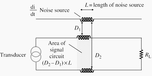
This depends on the rate of change of the noise current and the mutual inductance between the noise system and the signal wires.
Expressed slightly differently, the degree of noise induced by magnetic coupling will depend on the:
- Magnitude of the noise current
- Frequency of the noise current
- Area enclosed by the signal wires (through which the noise current magnetic flux cuts)
- Inverse of the distance from the disturbing noise source to the signal wires.
The effect of magnetic coupling is shown in Figure 1 below.

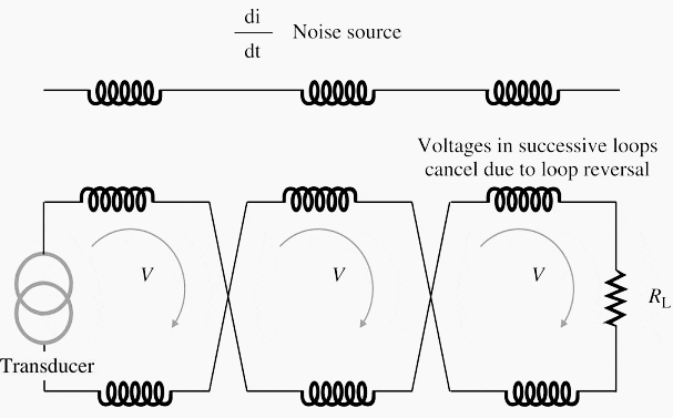
The easiest way of reducing the noise voltage caused by magnetic coupling is to twist the signal conductors. This results in lower noise due to the smaller area for each loop.
Hence an even number of loops will tend to have the noise voltages canceling each other out. It is assumed that the noise voltage is induced in equal magnitudes in each signal wire due to the twisting of the wires giving a similar separation distance from the noise voltage (see Figure 3).

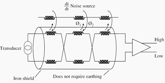
The second approach is to use a magnetic shield around the signal wires (refer Figure 4).
The magnetic flux generated from the noise currents induces small eddy currents in the magnetic shield. These eddy currents then create an opposing magnetic flux Φ1 to the original flux Φ2. This means a lesser flux (Φ2 − Φ1) reaches our circuit!

Note: The magnetic shield does not require earthing. It works merely by being present. High-permeability steel makes best magnetic shields for special applications. However, galvanized steel conduit makes a quite effective shield.
4. Radio frequency radiation
The noise voltages induced by electrostatic and inductive coupling (discussed above) are manifestations of the near field effect, which is electromagnetic radiation close to the source of the noise.
The effects of electromagnetic radiation can be neglected unless the field strength exceeds 1 V/m. This can be calculated by the formula:

where field strength is in volt/meter, power is in kilowatt and distance is in kilometer.
The two most commonly used mechanisms to minimize electromagnetic radiation are:
- Proper shielding (iron)
- Capacitors to shunt the noise voltages to earth.
Any incompletely shielded conductors will perform as a receiving aerial for the radio signal and hence care should be taken to ensure good shielding of any exposed wiring.
Reference: Practical Grounding, Bonding, Shielding and Surge Protection – G. Vijayaraghavan, B.Eng (Hons) Consulting Engineer, Chennai, India


So you cant bring walkie talkies near to power cables.