
Estimated Study Time: 34 minutes
400kV Bus Reactor Protection Systems
The technical article provides a highly detailed analysis of the Reactor Troubles Circuit schematics. It systematically breaks down the contact multiplication stage, the core mechanical protections (Buchholz, WTI, SPR), and the pressure/thermal protections (PRD, PNRV, OTI). Each component is mapped directly to the schematic grid references (page, row, and column) and explained in strict accordance with its operational physics and integration into the broader 400kV bay architecture.
 Technical Analysis of 400kV Reactor Troubles Circuit Schematics
A download link for the complete PDF document with drawings (114 pages) can be found at the beginning of this article. Open it up, so you can follow the discussion.
Why 400kV bus reactor is used: The integration of 400kV bus reactors is a critical engineering component in high-voltage transmission networks, primarily responsible for compensating capacitive reactive power generated by long, lightly loaded transmission lines. Due to the immense operational stresses placed on these shunt reactors, robust, deterministic, and highly reliable protection schemes are absolutely mandatory to prevent catastrophic equipment failure and subsequent grid instability.
Unlike conventional electrical protection relays (such as differential or impedance protection) that continuously analyze current and voltage waveforms via Current Transformers (CTs) and Voltage Transformers (VTs), mechanical protection devices directly monitor the physical state of the reactor tank and its primary insulating medium.
These states encompass internal dynamic pressure, oil temperature, calculated winding hot-spot temperature, and the accumulation of combustive fault gases. When an internal fault occurs—such as an inter-turn short circuit, a core insulation failure, or dielectric breakdown—localized arcing causes the rapid decomposition of the hydrocarbon-based dielectric mineral oil.
This chemical decomposition instantly generates fault gases (predominantly hydrogen, acetylene, and methane) and localized pressure shockwaves. The physical sensors installed directly on the reactor tank detect these severe physical anomalies and transmit discrete Direct Current (DC) signals via extensive control cabling to the Control and Protection (CRP) panel located in the substation control room.
Furthermore, these critical signals are distributed to Intelligent Electronic Devices (IEDs) for accurate event logging, Generic Object-Oriented Substation Event (GOOSE) messaging across the IEC 61850 station bus, and the immediate initiation of specialized active suppression systems such as the Nitrogen Injection Fire Protection System (NIFPS).
The following sections deconstruct each schematic reference, detailing the exact location, operational physics, ferrule numbering conventions, and intricate logic routing of every primary component within the Bay-402 architecture.
Schematics (PDF, 6.2 MB)
- General Circuit Architecture, Ferrule Numbering, and Auxiliary Relays:
- Detailed Analysis of SHT 032: Core Mechanical Protections:
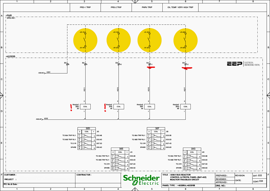
- Detailed Analysis of SHT 033: Pressure and Thermal Protections:
- Analysis of SHT 034 and SHT 035: Contact Distribution & Tripping Matrix:
- Integration with Bay Architecture, Lockout Relays, and IEC 61850
- Let’s Make a Conclusion
- ATTACHMENT (PDF) 🔗 Download ‘Modern Digital Protective Schemes for Power Transformers’
1. General Circuit Architecture, Ferrule Numbering, and Auxiliary Relays
Before examining the isolated individual mechanical protection functions, it is essential to establish a firm understanding of the intermediate contact multiplication stage and the standardized wiring conventions utilized within the Schneider Electric panel design.
1.1 Standardized Ferrule Numbering Conventions
According to the “List of Symbols” detailed on Sheet 001 (Page 12), the wiring schematic strictly adheres to an alphanumeric ferrule numbering standard that denotes the specific function of the wire. This guarantees organized fault tracing and precise isolation during maintenance.
The primary ferrule prefixes applicable to the Reactor Troubles Circuit are:
- Prefix “J”: Denotes Auxiliary DC Circuits. Wires carrying the raw 220V DC supply from the DC Distribution Board (DCDB) to the panel isolation switches and fuse links are designated with ‘J‘ (e.g., J101, J103).
- Prefix “K”: Denotes Control Circuits. Wires actively carrying trip initiation logic, interlocks, and the manipulated DC rails following the auxiliary relays are designated with ‘K‘ (e.g., K101, K103, K201).
This strict segregation ensures that engineers analyzing the physical panel can instantly differentiate between a permanent power rail (‘J‘) and an actively switched control logic rail (‘K‘).
Figure 1 – The primary ferrule prefixes applicable to the Reactor Troubles Circuit (click to zoom)
1.2 Auxiliary Contact Multiplication Relays
Field sensors located on the reactor are typically equipped with low-current, single-pole dry microswitches. These singular field contacts are electrically insufficient to drive multiple, heavy-duty parallel circuits simultaneously due to current rating limitations, contact bounce phenomena, and the absolute necessity for strict galvanic isolation between primary and redundant protection groups.
Therefore, the Reactor Troubles Circuit employs a dedicated bank of high-speed auxiliary contact multiplication relays.
According to the Bill of Materials specified in the schematic documentation (Sheet 002, Page 4), the auxiliary relays utilized for mechanical trip multiplication are Schneider Electric type GBINSER-AAS4F220. These are high-speed, robust electromechanical contact multiplication relays operating at a nominal auxiliary voltage of 220V DC (+10% to -20% of Un).
However, the mechanical hand-reset flag remains prominently deployed on the front panel arrangement, providing a permanent, non-volatile visual indication to the substation operator regarding which specific trouble initiated the trip. This flag remains visible until it is manually acknowledged and physically reset by an engineer.
The 220V DC control voltage is sourced from the primary Direct Current Distribution Board (DCDB), ensuring complete independence from the alternating current (AC) station supply, which is highly susceptible to collapse during severe short-circuit events.
Figure 2 – Direct Current Distribution Board (DCDB) (click to zoom)
2. Detailed Analysis of SHT 032: Core Mechanical Protections
Sheet 032 of the schematics (documented on Page 43 of the supplied drawing set) meticulously outlines the primary mechanical fault inputs: the Buchholz Relay, the Winding Temperature Indicator (WTI), and the Sudden Pressure Relay (SPR).
These three parameters represent the most critical internal health indicators of a high-voltage oil-filled reactor and require instantaneous breaker clearance.
2.1 Buchholz Relay-1 Trip Circuit (Relay 30A)
Reference Location: Page 43, Row A, Column 2 (Input Terminals); Page 43, Row B, Column 2 (Relay Coil); Page 43, Rows C and D, Column 2 (Contact Distribution).
Operational Physics and Principle: The Buchholz relay is an indispensable gas and oil-actuated protective device installed inline within the pipework connecting the main reactor tank to the conservator tank. It operates on a highly reliable dual-float mechanical principle.
Minor, slowly developing faults (such as localized tracking, core bolt insulation failure, or low-energy partial discharges) produce small volumes of gas that accumulate in the upper chamber of the relay. This gradually displaces the oil and lowers the top float to trigger a non-tripping alarm.
The physical impact deflects the baffle, closing a magnetically coupled reed switch or a highly reliable mercury switch.
Figure 3 – Buchholz Relay-1 Trip Circuit (Relay 30A) (click to zoom)
Circuit Logic and Routing: The closure of the Buchholz field contact completes the electrical circuit across terminals -X1-28 and -X1-13 (located at Page 43, Row A, Column 2). This action routes the positive 220V DC rail through the field wiring and back into the CRP panel, actively energizing the coil of auxiliary relay 30A.
Once relay 30A is fully energized, its 4 C/O contacts change state (located at Page 43, Rows C and D, Column 2). The schematic dictates the following precise routing matrix for these highly critical contacts:
- Contact 1 (Terminals 1-2): Routed to the 86A TRIP RLY CKT (Grid reference /034.3B). This initiates the primary Group A Master Trip Relay, executing an unconditioned opening of the 400kV circuit breaker.
- Contact 2 (Terminals 3-4): Routed to the 86B TRIP RLY CKT (Grid reference /034.3D). This provides absolute redundancy by initiating the secondary Group B Master Trip Relay.
- Contact 3 (Terminals 5-6): Routed to the 87R TRIP RLY CKT (Grid reference /020.2C). This sends a direct hardware signal to the Bay-402 Differential Protection Relay (MICOM P643).The P643 utilizes this discrete opto-isolated input to log the exact millisecond event in its disturbance recorder, append the data to its Sequence of Events (SOE) log, and broadcast a GOOSE message across the IEC 61850 station bus to inform adjacent bays of a severe internal reactor fault.
- Contact 4 (Terminals 7-8): Routed to the NIFPS (Nitrogen Injection Fire Protection System) interface (Grid reference /093.5C).
Because a Buchholz trip frequently indicates a high-energy arcing fault with a severe risk of tank rupture and ensuing oil fire, this contact immediately arms or initiates the NIFPS.
The NIFPS responds by rapidly draining a portion of the top oil and injecting pressurized nitrogen gas from the base of the tank to stir the oil, cool the core, extinguish internal combustion, and prevent atmospheric oxygen from sustaining a fire.
Related electrical guides & articles


Edvard Csanyi
Hi, I'm an electrical engineer, programmer and founder of EEP - Electrical Engineering Portal. I worked twelve years at Schneider Electric in the position of technical support for low- and medium-voltage projects and the design of busbar trunking systems.I'm highly specialized in the design of LV/MV switchgear and low-voltage, high-power busbar trunking (<6300A) in substations, commercial buildings and industry facilities. I'm also a professional in AutoCAD programming.
Profile: Edvard Csanyi
