
Estimated Study Time: 3 minutes
Parallel operation of transformers
In perfect parallel operation of two or more transformers, current in each transformer would be directly proportional to the transformer capacity, and the arithmetic sum would equal one-half the total current.
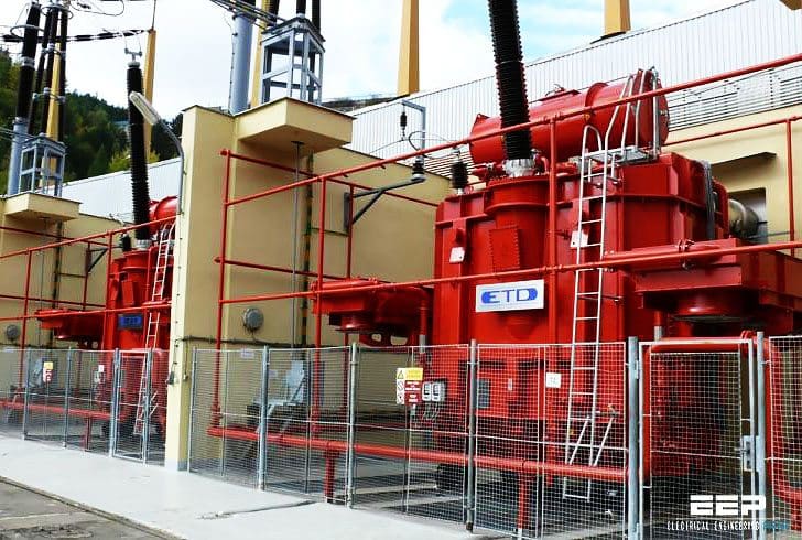 5 conditions for perfect parallel operation of single phase transformers (photo credit: etd-bez.cz)
In practice, this is seldom achieved because of small variations in transformers. However, there are 5 conditions for operating transformers in parallel and they are:
Condition #1
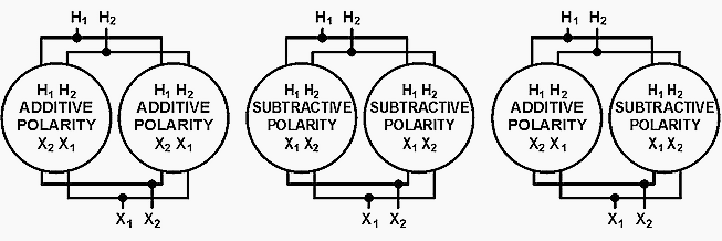
Any combination of positive and negative polarity transformers can be used. However, in all cases, numerical notations must be followed on both primary and secondary connections. That is H1 connected to H1, H2 connected to H2, and X1 connected to X1, X2 connected to X2, X3 connected to X3.
Note that each subscript number on a transformer must be connected to the same subscript number on the other transformer as shown in figure 1.
CAUTION:
With positive and negative polarity transformers, the location of X1 and X2 connections on the tanks will be reversed. Care must be exercised to ensure that terminals are connected, as stated above. See figure 1 above.
Condition #2
Tap settings must be identical.
Condition #3
Voltage ratings must be identical; this, of course, makes the turns ratios also identical.
Condition #4
The percent impedance of one transformer must be between 92½% and 107½% of the other. Otherwise, circulating currents between the two transformers would be excessive.
Condition #5
Frequencies must be identical. Standard frequency in the United States is 60 hertz and usually will not present a problem.
However, to meet the percent impedance requirement, they must be nearly the same size! Most utilities will not parallel transformers if they are more than one standard kVA size rating different from each other. Otherwise, circulating currents are excessive.
Reference // Transformers: Basics, Maintenance, and Diagnostics – U.S. Department of the Interior Bureau of Reclamation
Related electrical guides & articles


Edvard Csanyi
Hi, I'm an electrical engineer, programmer and founder of EEP - Electrical Engineering Portal. I worked twelve years at Schneider Electric in the position of technical support for low- and medium-voltage projects and the design of busbar trunking systems.I'm highly specialized in the design of LV/MV switchgear and low-voltage, high-power busbar trunking (<6300A) in substations, commercial buildings and industry facilities. I'm also a professional in AutoCAD programming.
Profile: Edvard Csanyi

am interested in your articles
i will be grateful to receive articles on parallel of power transformers
In a school & college building, two transformers having separate PFI panels are supplying different areas of the premises.They show 0.95 power factor and above individually. Recently, when the 2nd transformer was installed the utility company gave a single source of 11 KV underground cable through a ring main unit (RMU). Thereafter the common meter recorded a lower power factor (below 0.95) for the combined load of two transformers.
What may be the reason behind lower power factor reading by the common meter whereas the individual transformers are showing standard power factor (above 0.95)?
sir, what about the phase correction? Which groups of 3 phase transformers can be connected in parallel?
What about the phase shift ??
Hallo, there is probably a mistake in the Figure 1, third schematic.