Efficient joints in copper busbar conductors
Efficient joints in copper busbar conductors can be made very simply by:

Bolting and clamping are used extensively on-site. Shaped busbars may be prefabricated by using friction stir welding.
1. Bolted joints (most common)
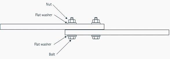
Bolted joints are formed by overlapping the bars and bolting through the overlap area. They are compact, reliable and versatile but have the disadvantage that holes must be drilled or punched through the conductors, causing some distortion of the current flow in the bar.
They can be assembled on-site without difficulty.

2. Clamped joints (most common)
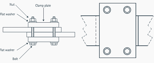
Clamped joints are formed by overlapping the bars and applying an external clamp around the overlap. Since there are no bolt holes, the current flow is not disturbed resulting in lower joint resistance. The extra mass at the joint helps to reduce temperature excursions under cyclic loads.
Well-designed clamps give an even contact pressure and are easy to assemble, but take up more space than a bolted joint and are more expensive to manufacture.

3. Riveted joints (difficult, but…)
Riveted joints are similar to bolted joints. They can be efficient if well made. It is difficult to control the contact pressure. They cannot easily be dismantled or tightened in service and they are difficult to install.

4. Soldered or brazed joints (rare)
Soldered or brazed joints are rarely used for busbars unless they are reinforced with bolts or clamps since heating under short-circuit conditions can make them both mechanically and electrically unsound.

5. Welded joints (not very safe…)
Welded joints are made by butting the ends of the bars and welding. They are compact and have the advantage that the current-carrying capacity is unimpaired, as the joint is effectively a continuous copper conductor. However, it may not be safe or desirable to make welded joints in situ.
Welding of copper is discussed in Copper Development Association Publication 98, Cost-Effective Manufacturing: Joining of Copper and Copper Alloys (Download here).

Joint Resistance Calculation
In principle, a clamped or bolted joint is made by bringing together two flat surfaces under controlled (and maintained) pressure, as shown in Figure 6.

The resistance of a joint is mainly dependent on two factors:
- The streamline effect or spreading resistance, Rs, due to the diversion of the current flow through the joint
- The contact resistance or interface resistance of the joint, Ri.
The total joint resistance, Rj, is given by:
Rj = Rs+ Ri
This applies specifically to direct current applications. Where alternating currents are flowing, the changes in resistance due to skin and proximity effects in the joint zone must also be taken into account.
Reference // Copper for Busbars – Guidance for Design and Installation – Copper Development Association (Download guidance)
Copyright Notice
This technical article is protected by U.S. and international copyright laws. Reproduction and distribution of PDF version of this technical article to websites such as Linkedin, Scribd, Facebook and others without written permission of the sponsor is illegal and strictly prohibited.© EEP-Electrical Engineering Portal.
Related electrical guides & articles
Premium Membership
Edvard Csanyi
Hi, I'm an electrical engineer, programmer and founder of EEP - Electrical Engineering Portal. I worked twelve years at Schneider Electric in the position of technical support for low- and medium-voltage projects and the design of busbar trunking systems.I'm highly specialized in the design of LV/MV switchgear and low-voltage, high-power busbar trunking (<6300A) in substations, commercial buildings and industry facilities. I'm also a professional in AutoCAD programming.
Profile: Edvard Csanyi


Hi is it best to have a dry joint with copper busbar bolted , or not thanks,
I read this guide from Copper Alliance too. I do not see anything on joints where two differently sized pieces of copper bus are connected.
I have an application in which I have a 6″x.5″ copper piece that needs to join a 4″x1.5″ piece. Anyone have any information about this?
Hello
I just had our 440V main 3200AT ACB replaced with a new one due to the old one was already 20 years and can no longer be open or close the contacts.
Due to difficulty and inexperience of the contractor for modifying the bus bar connections, he mostly dismantled the whole bus bar assembly of the 440V switchgear and enlarged n mostly doubled the hole size for the bolt connections. This is for him to be able to make adjustments and movements to fit the bus bars to new ACB terminal connectors.
My question is – what is the effect of the bolt holes which are now larger than the installed bolts? He just managed to fit n jont the bus bar plates thru use of washers. My worry is the holes are larger and may affect the current flow.
Can you give me the potential problems that may arise due to this?
Thank you in advance.
what should be the bolt material for electrical connections, give reference if possible
I am also interested in this subject matter. A contractor installed an MV switchgear in which bare copper grounding bus bar and bare copper terminal was fastened by a carbon steel galvanized bolt. Is dissimilar material OK to be used?
I am practicing my electrical profession, Currently in Georgia, Kindly help about the busbar inter-connection
between panels. because the supplier delivered a busbar to the end panels connected in two bolts only same in two end panels. supplier said this for the future extension connection for the two remaining holes.
is there any effect on the busbar connected with two bolts only. not in full contact with the whole width of the busbar. the horizontal position in contact with half of the width of the vertical busbar with two bolts connection.
I DONT AGREE WITH COMMENT ABOUT COPPER LUGS ON ALUMINIUM CABLES HAVE JOINED COPPER LUGS TO AL. CUTTING STRANDS AND USING VEG. OIL FLUX & 80/20 SOLDER PLACING CRIMP VERTICAL GLASS TAPE BOTTOM OF LUG INSERTING FLUX & SOLDER THROUGH SLOT IN THE TOP OF CRIMP LUG
Hi Edvard Csanyi
I am mohamed mow only i started my career as a electrical draftsman in switchgear industry, please give me some tips to make a own control circuit because making a new control circuit is much more harder for me so please help me to develop my carrier .
Dear Edvard ,
What about contact between tin plated copper bus bars with silver plated part of CB bur or CB ” out “and “incom” connector ( this applies both to the networks medium and low voltage) .
This problem exist for systems operating in H2S atmosfere
B.R.
David
Should add to bolted connections that selection of bolt material is important as well as the addition of compression washers.
Isn’t there a specific code rule in the CEC that states concave washers must be used to install bolted busbars together
Dear Edvard Congratulations for this article and others that you have been writing. I am interested in more details about soldering and welding of busbars for high permanent currents like 10.000A . Can you indicate some literature ?
Hi Edvard,
The article is very good and simple. Can you go deeper in the overlap area calculation ?
For copper to copper : mm²/A and daN
Same for Alu to Alu
And a special notice for the use of different material : alu/copper AND the use of magnetic steel for the clamp due to induced current.
(I can give you some figures if needed up to 6300A)
Regards
Bertrand COHARD
Hello, I agree with Bertrand. Also add how many screws per overlap